MTS 793 Controller Hardware FlexTest GT Controller Connections
119
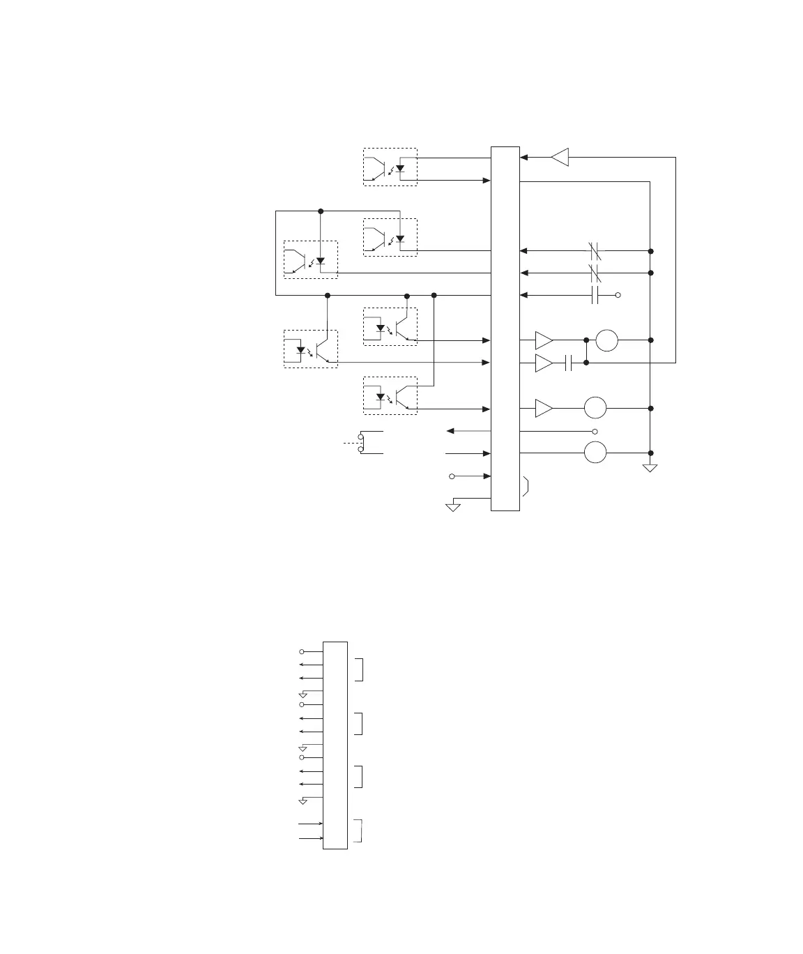
J25 Diagram
System I/O Connector J54 Sys I/O provides three digital inputs and one digital
output. The inputs are connected to the high and low inputs of an
opto-isolator. The output is from the collector (+) and emitter (-). See
the “Digital I/O Connections” on page 126 for circuit drawings.
To/From
HPU
9
10
11
12
1
2
3
4
5
6
7
8
Controller 24 Vdc
J25To/From
Chassis
To J24 pin 13
To J29 pin 8
E-stop
HPS On
Sense
HPS 24 Vdc
Start
Lo
High
Over Temp
Low Level
+24
vdc
CRM
Motor
Relay
SOL
CRM
+24 Vdc
1CR
Start
Relay
Hi Pressure
Solenoid
HPS Interlock
Relay
HPS Defeat Voltage
(not connected in HPS)
+
-
+
-
+
-
+
-
+24 V
+24 V
+24 V
Input 1
Output 1
Input 3
Input 2
To/From
External
Devices
1
2
3
4
5
6
7
8
9
10
11
12
13
14
15
J54
To/From
HPU
Artisan Technology Group - Quality Instrumentation ... Guaranteed | (888) 88-SOURCE | www.artisantg.com