MTS 793 Controller Hardware FlexTest IIm Controller Connections
195
Task 1 Cable your controller to the readout device.
Cable your FlexTest IIm analog output connector to the readout
device. Analog I/O connectors are located on the rear of the test
processor chassis.
Connect a 498 Analog Out connector to the external readout device
analog input.
Task 2 Create a readout channel with Station Builder.
Refer to “How to Create a Readout” in the MTS 793 Control Software
manual for more information.
Task 3 Adjust the readout signal in Station Manager.
Use Station Manager to adjust the readout signal.
For a detailed description of readout signal configuration and
adjustment, refer to “How to Configure a Signal for External Readout”
in the MTS 793 Control Software manual for more information.
J11
(CH 1-4)
J12
(CH 5-8)
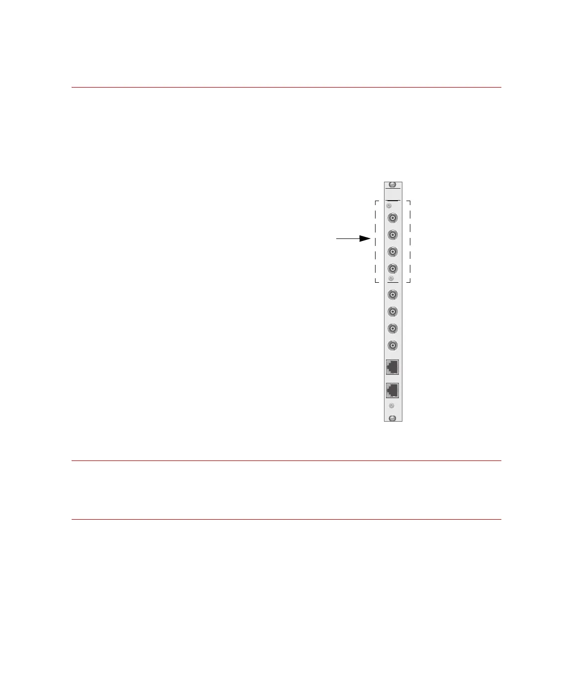
498
ANALOG
OUT
CH 1
CH 2
CH 3
CH 4
CH 5
CH 6
CH 7
CH 8
98 Analog Out
his module includes 8 BNC
connectors that provide analog
outputs from the 498.65 ADDA
module.
Four analog outputs are available
ith the standard ADDA module.
he other four outputs require a
second ADDA module.
Artisan Technology Group - Quality Instrumentation ... Guaranteed | (888) 88-SOURCE | www.artisantg.com