MTS 793 Controller Hardware
FlexTest GT Controller Connections
96
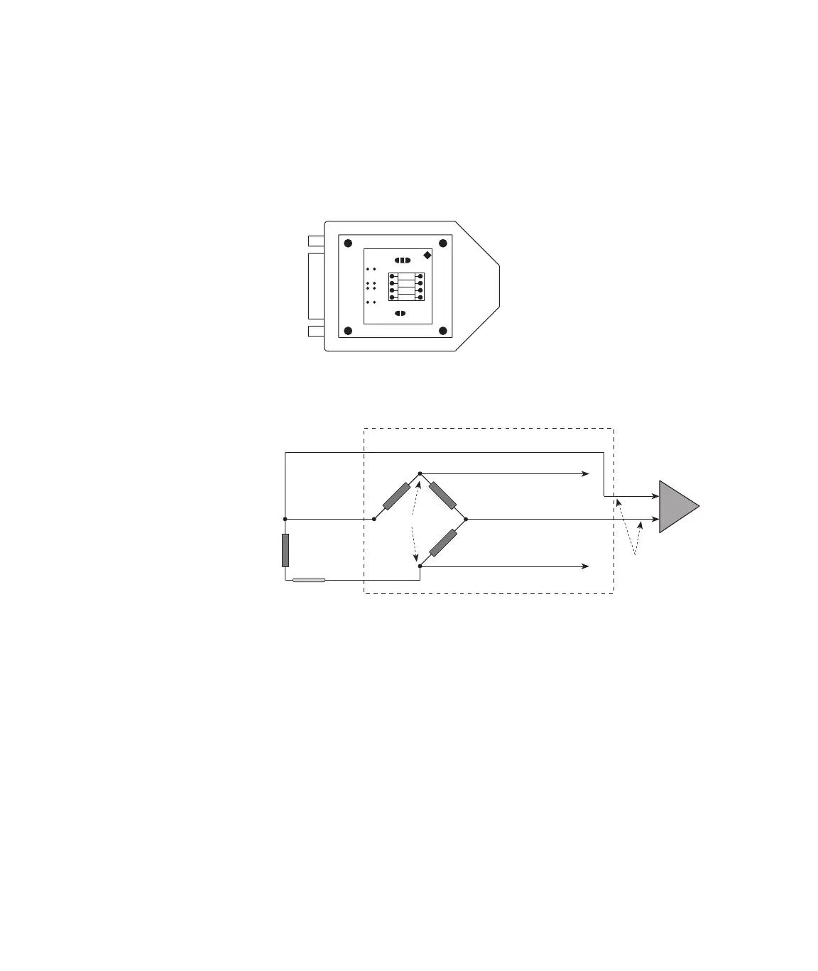
The circuit card has the bridge completion and shunt calibration
resistors on one side, and the transducer ID circuit on the other.
• R6, R7, and R8 are the bridge completion resistors
• R9 is the shunt calibration resistor
The following is the schematic diagram of the bridge balance and
bridge completion circuit.
Note Refer to the MTS 793 Control Software manual for information
about assigning sensors and saving data with Transducer ID
Modules.
l
W1
W2
1
2
3
SC
R6
R7
R8
R9
+EX
-FB
+FB
Vout
Pre-amp
-EX
+FB
Rcomp (R8)
Rcomp (R7)
Rcomp
(R6)
Vin
-FB
-FBR
Rg
Sensor ID Module
Artisan Technology Group - Quality Instrumentation ... Guaranteed | (888) 88-SOURCE | www.artisantg.com