7.5 Valve Drive
7.5.1 Valve clearance – Check and adjustment
Preconditions
☑Engine is stopped and starting disabled.
☑Engine coolant temperature is max. 40 °C.
☑Valves are closed.
Special tools, Material, Spare parts
Designation / Use Part No. Qty.
Feeler gauge
Y4345893 1
Engine barring device
F6783914 1
Ratchet with extension
F30006212 1
Double-head box wrench
F30002800 1
Angular screw driver
F30002816 1
Socket wrench
F30030450 1
Torque wrench, 10–60 Nm
F30510423 1
Measuring instrument
Y4345888 1
Engine oil
Preparatory steps
1. Remove air filter (→ Page 107).
2. Remove cylinder head cover (→ Page 91).
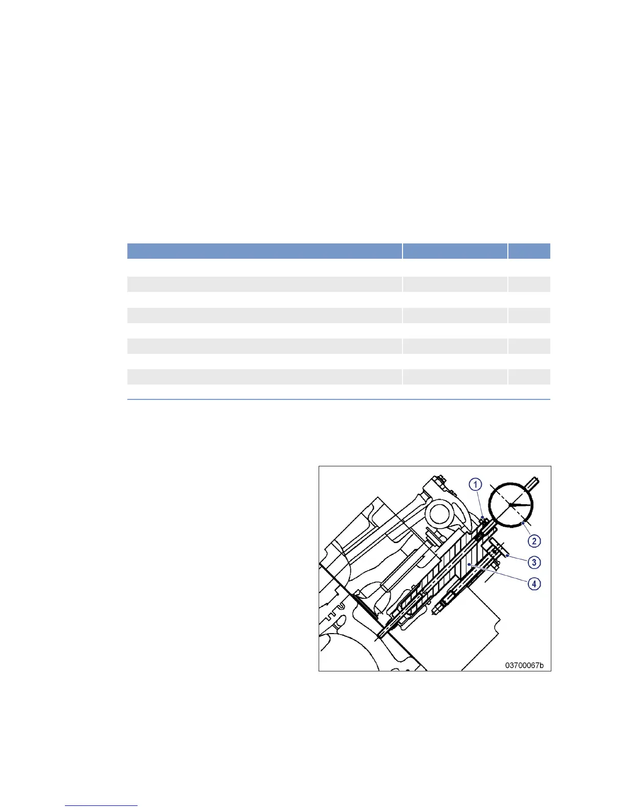
Positioning A1 piston at TDC
Note: With cylinder head and valve gear installed.
1. Insert preloaded dial gauge (2) into meas-
uring device (4) and secure using screw (1).
2. Install measuring device (4) in cylinder
head and secure using knurled screw (3).
3. Set dial gauge (2) to zero.
4. Turn engine using barring device until pis-
ton A1 reaches firing TDC.
Result: The piston is at firing TDC when both rock-
er arms are unloaded, i.e. have clearance.
88 | Task Description | M015655/05E 2015-06
TIM-ID: 0000050016 - 002