Removing injection pump
1. Mark installation position of injection pump.
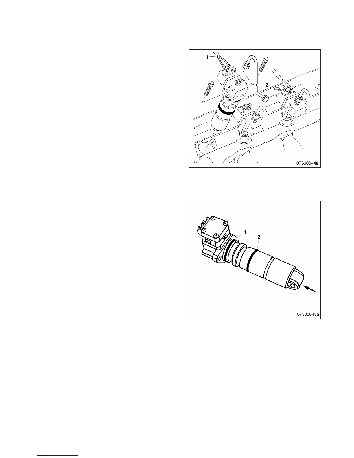
2. Disconnect wiring (1) from injection pump.
3. Remove fuel line (2).
4. Unscrew securing screws of injection pump
by approx. 6 mm.
Result: The pretensioned compression spring
presses the injection pump out of the crank‐
case. If not:
• Turn crankshaft with barring device
(→ Page 166) .
The pump cam at the camshaft presses
the injection pump out of the crankcase.
If not:
• Carefully force out injection pump at the
recess in the injection pump head.
5. Remove injection pump securing screws.
6. Remove injection pump.
7. Remove sealing rings from injection pump.
8. After removal, seal all openings with suita‐
ble covers.
Installing injection pump
1. Remove all blanking plugs and covers.
2. Clean mating face of injection pump and
roller.
Note: Sealing ring (1) Ø47 mm
3. Coat sealing ring (1) with grease (Kluthe
Hakuform 30-10/emulsifier) and fit on to in‐
jection pump.
Note: Sealing ring (2) Ø45 mm
4. Coat sealing ring (2) with grease (Kluthe
Hakuform 30-10/emulsifier) and fit on to in‐
jection pump.
5. Coat roller (arrow) with engine oil.
6. Clean sealing surface and fuel bores in
crankcase.
7. Use barring device (→ Page 166) to position
the pump cams on the camshaft at base cir‐
cle.
MW15550/06E 2012-02 | Task Description | 181
TIM-ID: 0000004579 - 003
 Loading...