MTX-xG-JAVA-IoT Family
www.mtxm2m.com 2017/07 v1.2 Page 47/105
MTX M2M® by MATRIX ELECTRONICA S.L.U
4.1 Power supply connector
Depending on the specific modem you are using, you will dispose of one of the connectors described
in the sections below. Please read them carefully.
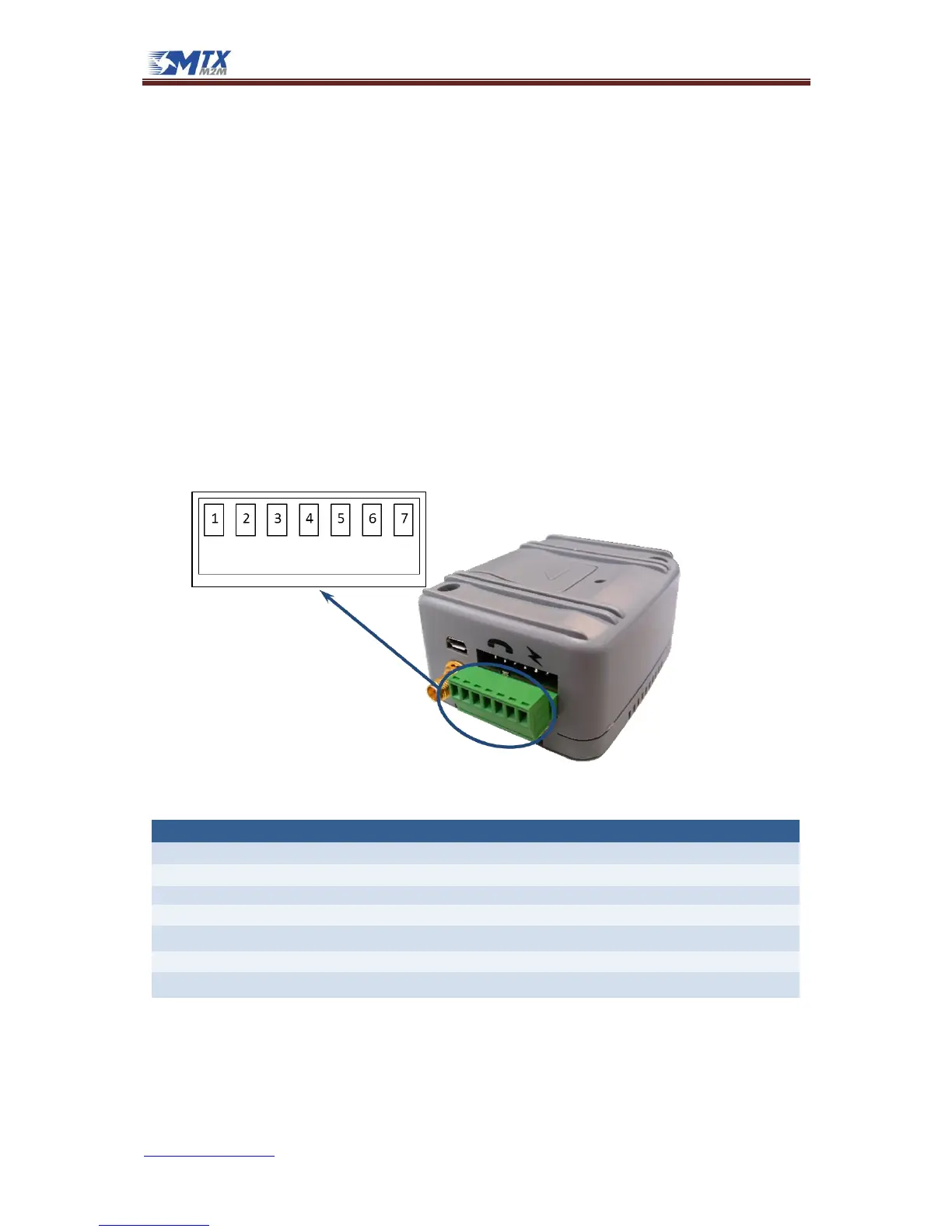
4.1.1 Models with CAN bus, 1-Wire and/or Latch Relay (7-way plug-in 3.50mm pitch
terminal block)
A 7-way plug-in terminal block connector shared with CAN & 1-Wire buses, as well as a Latch relay,
supplies the D.C. power to the modem.
The supply voltage, VCC, required by the modem is in the range of 7 to 50VDC. We recommend a
12VDC power supply. The power supply has to be a single voltage source capable of providing a peak
during an active transmission. The uplink burst causes strong ripples (drop) on the power lines.
By default, the MTX-IoT will automatically switch on when power supply is applied at PIN 1 and PIN 2.