MTX-xG-JAVA-IoT Family
www.mtxm2m.com 2017/07 v1.2 Page 59/105
MTX M2M® by MATRIX ELECTRONICA S.L.U
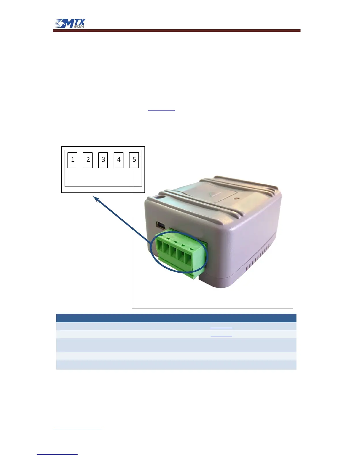
4.5 RS485 bus
The STD models have a terminal block with a 5-way connector shared with the Power Supply section,
as shown and described below, used to implement the RS485 interface.
Port signals +RxA and –RxB are connected to an internal coprocessor through a transceiver. In the STD
model, which has two RS232 and a RS485 port, this coprocessor selects which of those ports are
connected to the Cinterion GSM engine’s UARTs ASC0 and ASC1. Users can select the ports configuring
the decice’s DIP switches. Please read section 4.7 to learn how to configure DIP switches in order to
select the port of your choice.
It meets or exceeds the requirements of ANSI TIA/EIA-485-A.
Automatic Restart after Shutdown Enable Signal (not available
in MTX-65i-RS485 FW2.00 (AUTO-ON) and MTX-65i-RS485-LC)