Section 75 00-02-0522
04-06-11 - 48 -
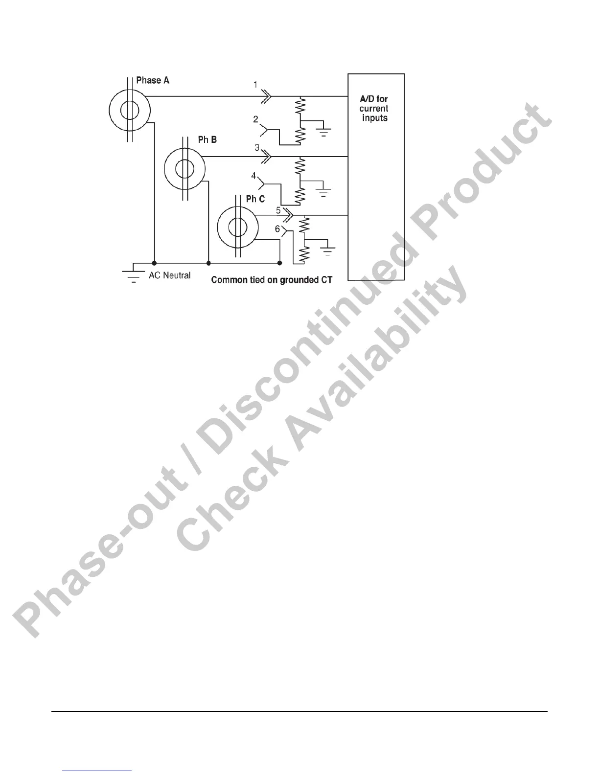
In fully differential connections, wire CT1+ to J10-1 to J10-2, etc. For commoned CT
connections bring CT1+ to J10-1, CT2+ to J10-3 and CT3+ to J10-5. Connect CT1-, CT2-, and
CT3- together and then connect to AC neutral. There is no need to jumper J10-2, 4 and 6 to
anything, although you can connect them to AC neutral if you wish.
There is a software selection in the iGUARD that must be set appropriate to the connection
method you are using. See Operating Sequence in the iGUARD Operating Instructions section
in this document.
The measuring method in the iGUARD controller requires that AC neutral and earth remain
with 1/2 VDC for accurate measurements, and within 6 VDC to prevent damage to the Energy
monitoring board (EMB). The controller offers a low impedance path to neutral (˜.025 Ω) so
the common mode voltage will be within a safe range.
Commercially Available Connectors
Connections to the iGUARD are via Molex connectors, MiniFit Jr. (for white/opaque white
signal level connectors), and Sabre series (for black EMB AC voltage and current connectors).
12 foot long harnesses are available from Murphy (see “Options and Accessories” section).
If you elect to build your own wire harnesses the following information on manufacturer’s part
numbers will be useful.
Connector Part Numbers
The MiniFit Jr. Series of connectors requires a crimping tool (such as a universal crimper) to
properly terminate the connectors. When terminating multiple wire harnesses, contact your
local Molex distributor for information on automated termination tooling.
Phase-out / Discontinued Product
Check Availability