Section 75 00-02-0522
04-06-11 - 51 -
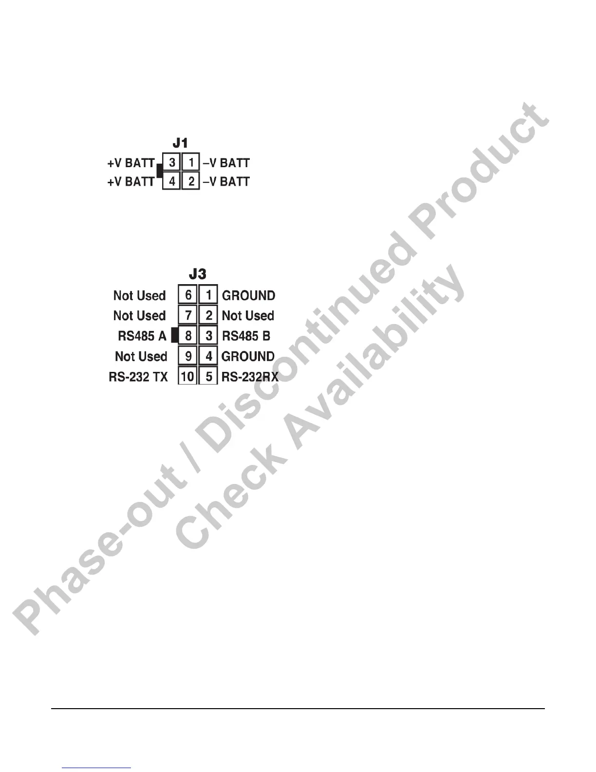
J1 Power Connector
The iGuard Mimic / Annunciator is powered using the J1 connector. The connector is wired as
shown below:
J3 Communications Connector
The iGuard Mimic / Annunciator communicates with the host iGUARD controller via a RS485
two-wire + shield connection. The connector is wired as shown below:
1. To configure the DM/A for a particular application do the steps as follows:
2. Press the BACK & NEXT keys at the same time.
3. The screen will change to identify the hardware/software as configured.
4. Press NEXT. The top line will display the station number.
The menus are as follows:
1. Modbus server address - This is the address of this device as seen on the network.
Default is 243.
2. Key sensitivity level - This sets the required amount of force to activate the keypad.
Default is Normal
3. LCD backlight - This selects whether the LCD backlight is enabled or not. If disabled, the
backlight will not come on. Default is enabled
4. iGUARD beeper - This selects whether or not the station beeper is enabled. If disabled, the
station will not sound any audible alarm for faults or warnings. Default is enabled.
5. Interface type - hard coded to RS485 Modbus
6. RS485 bit frame - Sets the configuration of the data transmission. Default (to match the
iGUARD default) is 10 bits N-8-1.
Phase-out / Discontinued Product
Check Availability