2205B0JE-DA-J-N_2014.05.
5 Maintenance and Inspection
Screw Compressor J-series 5.4 Disassembly and Assembly of the Compressor
5-41
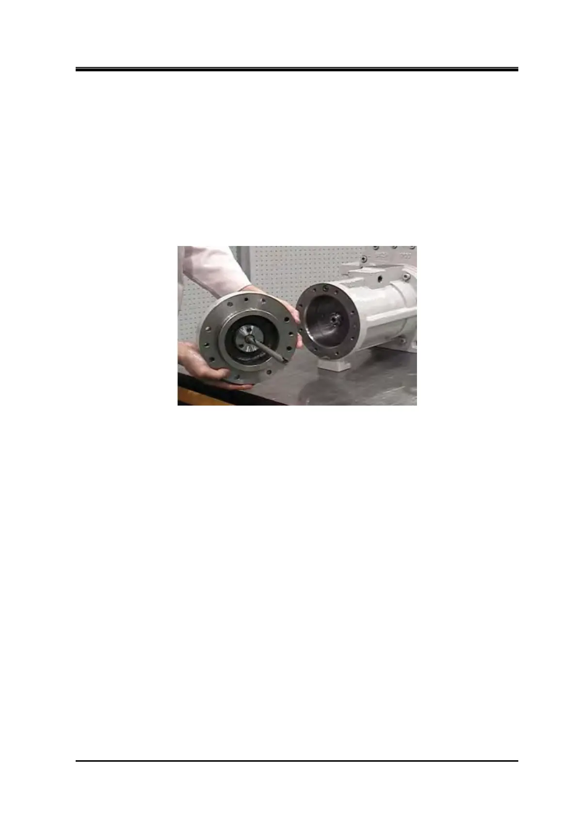
Unloader cylinder cover assembly
1. The unloader indicator cam groove opening must face upwards, when installing into the unloader
slide valve push rod pin.
2. Install the unloader assembly to the unloader cylinder with the diagonal service holes of the
unloader cover horizontal, and with one of the three tap holes for unloader indicator assembly
above the horizontal service holes.
3. Check that the cam rotates smoothly by moving the unloader cover assembly back and forth
horizontally.