GT 710-8710 Swing Door System Low Energy Operator www.NabcoEntrances.com
Part #15-10683 Rev. 9-24-14
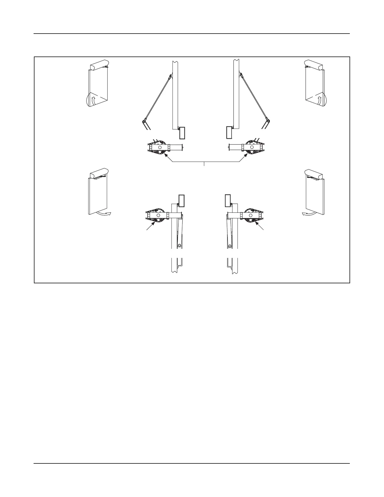
7-22 Install the Magnets
DN 1126
DN 0062
DN 0063
DN 0064
DN 0065
LEFT HAND
OUTSWING
RIGHT HAND
OUTSWING
ALL MAGNETS MUST BE INSTALLED WHITE SIDE UP
Back Check
Magne c Switch
DOOR FULLY OPEN
DOOR FULLY OPEN
DOOR FULLY OPEN DOOR FULLY OPEN
RIGHT HAND
INSWING
Back Check
Magne c Switch
Back Check
Magne c Switch
LEFT HAND
INSWING
Figure 7-2 Install the Back Check Magnet
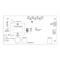
5.1.1 Test the Back Check Magnet
When the Magnet is correctly set, the Green LED on the Magnum 4A Control will be:
X ON steady when the Swing door is in the fully Open position after an activation.
Turn Power ON.
Electronically open the Swing door.
a. The Main Sprocket Gear rotates as the Swing door opens/closes.
b. As the Main Sprocket Gear rotates so do the Magnets.
c. As the Swing door opens to the 75 degree mark, the Back Check Magnet starts to rotate
underneath the “Back Check” Magnetic Switch. The Swing door will start to slow down.
d. At the 90 degree mark, the Back Check Magnet is fully underneath the Magnetic Reed Switch.
a. The Swing door stays open until the timer counts down.
a. Please refer to Magnum 4A Control Wiring and Adjustment Manual P/N 15-10682 for
additional information.
Relocate the Magnet if adjustment is deemed necessary.