75
English
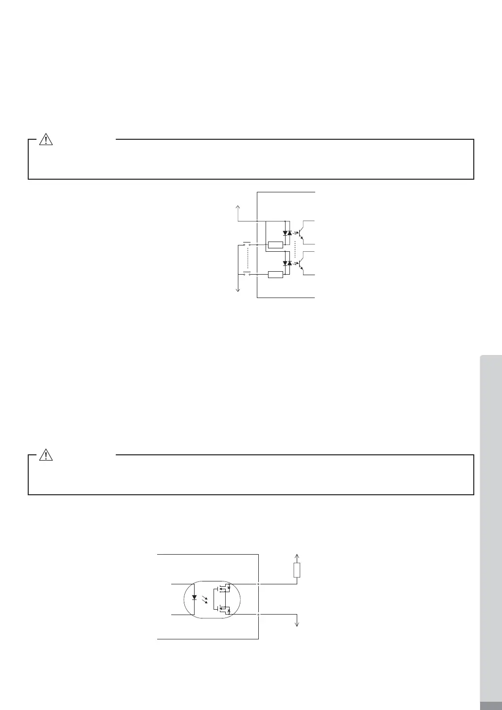
(3) Input / Output Signal
① Input Signal
There are 8 different input signals : " Rotate Command (START) ", " Rotating Direction Setting (DIR_IN) ",
" Rotates Motor at ' Centering ' Rotation Speed (500min
-1
(rpm)) ", " Error Release (RESET) ", " Count
Pulse Signal for Setting Motor Speed (CNT_IN) ", " UP / DOWN Signal for Setting Motor Speed (UD_IN) ",
" Speed Point Select 0 (SEL0) " and " Speed Point
Select 1 (SEL1)" . These signals are DC+24V signals
from an external signal source.
Please use a separate power source that is capable of supplying DC+24V ± 10%, 100mA.
Fig. 26
DC+24V or DC 0V
1
(
COM_1
)
DC 0V or DC+24V
The side of CONTROLLER
② Output Signal I
There are 5 separate output signals: " Rotating (RUN) ", " Rotating Direction (DIR_OUT) ", " Error (ERR) ",
" Warning (WARNING) " and " Speed Achievement (COIN) ". These signals are MOSS Relay Contact
Connections. The output current can be connected to either sinking or sourcing.
Voltage and Current Speci¿cations
・Applied Voltage (V) ≦ DC+30V
・Working Current (lp) ≦ 100mA
Refer to Fig.
27 for connections.
DC+24V or DC 0V
DC 0V or DC+24V
(
COM_2
)
18
6, 7, 8, 20, 21
Load
The side of CONTROLLER
Fig. 27
CAUTION
Do not use a power supply of more than DC+24V. This will cause damage to the CONTROLLERS
I / O Board.
CAUTION
Never supply more that 100mA of current to the input / output circuit. It is highly recommended to
add a LOAD (resistor) to the output circuit. Over Current Will Cause Damage to the CONTROLLER.
Use an external power source for output circuits. It is recommended to use the same DC+24V power source used
for input signals. Please refer to Fig. 27 for connections.
 Loading...