11 Accelaterm
®
Installation and Service Manual
Incoming Power
Knockout
Cable and Wiring Categories
The wiring and cabling for the Accelaterm are divided into
three categories:
Mains Power Cables and Wiring
This category contains Mains AC power cables servicing the
Accelaterm Panel. The connection to the mains must be car-
ried out by qualified personnel.
Low-Voltage Power and Accessory Relay Devices
12 or 5 Volt Reader Power, any accessory relay controlled de-
vices connected to the Panel, and any 12 Volt Accessories re-
ceiving battery-backed power from the panel. (These are
power-limited circuits, and normally do not require a licensed
electrician to complete this work). All power-limited wiring to
remain ABOVE the shelf (shown in the image below). Do not
allow power-limited wiring to cross over circuit boards.
Communication Cables
This category contains all the communication cabling between
the Accelaterm and all communication equipment, all alarm
circuits, and all card reader devices. (These are power-limited
circuits, and normally do not require a licensed electrician to
complete this work). All power-limited wiring to remain
ABOVE the shelf (shown in the image below). Do not allow
power-limited wiring to cross over circuit
boards.
Note: For proper operation of the Ac-
celaterm, route EACH category of cabling in
SEPARATE conduit or bundle (i.e., DO NOT
mix alarm and communication cables in the
same conduit as relay and power cables). Ple-
num-Rated cabling may be required in certain
installations. See Important Safety Information, page 6.
Incoming Power Conduit Knockout
The Accelaterm System requires [120VAC, 2A, 60Hz] --or--
[230VAC, 1A, 50Hz] voltage to the AC Input Power Terminal
Block (see page 12). The power cabling is delivered to the
Accelaterm through a knockout located on the lower right side
cabinet wall (see Figure 5). The 3/4 inch knockout accepts
EIA standard conduit connectors. Connection must be made to
metal enclosed Class 1 wiring system.
Note: This system must be installed indoors
within the protected premise in accordance with
the National Electrical Code (NFPA70), local
codes, and the authorities having jurisdiction.
Accessory Conduit Knockouts
All cabling for the Accelaterm is routed through EIA standard
knockouts located on the left and right sides of the cabinet (see
Figure 5). On the top of the enclosure, three-size knockouts
are available.
Grounding Accessory Drain and Shield Wires
Ensure electromagnetic compatibility and reliable performance
by keeping all accessory drain and shield wires as short as pos-
sible.
All accessory drain and shield wires connect to ground posts
mounted along the knockout strips on both sides of the Ac-
celaterm cabinet (see Figure 5).
The following procedures assure proper installation of all drain
and shield wires.
• Carefully remove the cable jacket after the cable enters the
Accelaterm cabinet.
• Place the drain wires under the ground post screw. Trim
as needed.
• Verify a good connection and tighten the ground post
nuts.
• Connect the accessory wires to the appropriate terminal
strip on the Accelaterm circuit board.
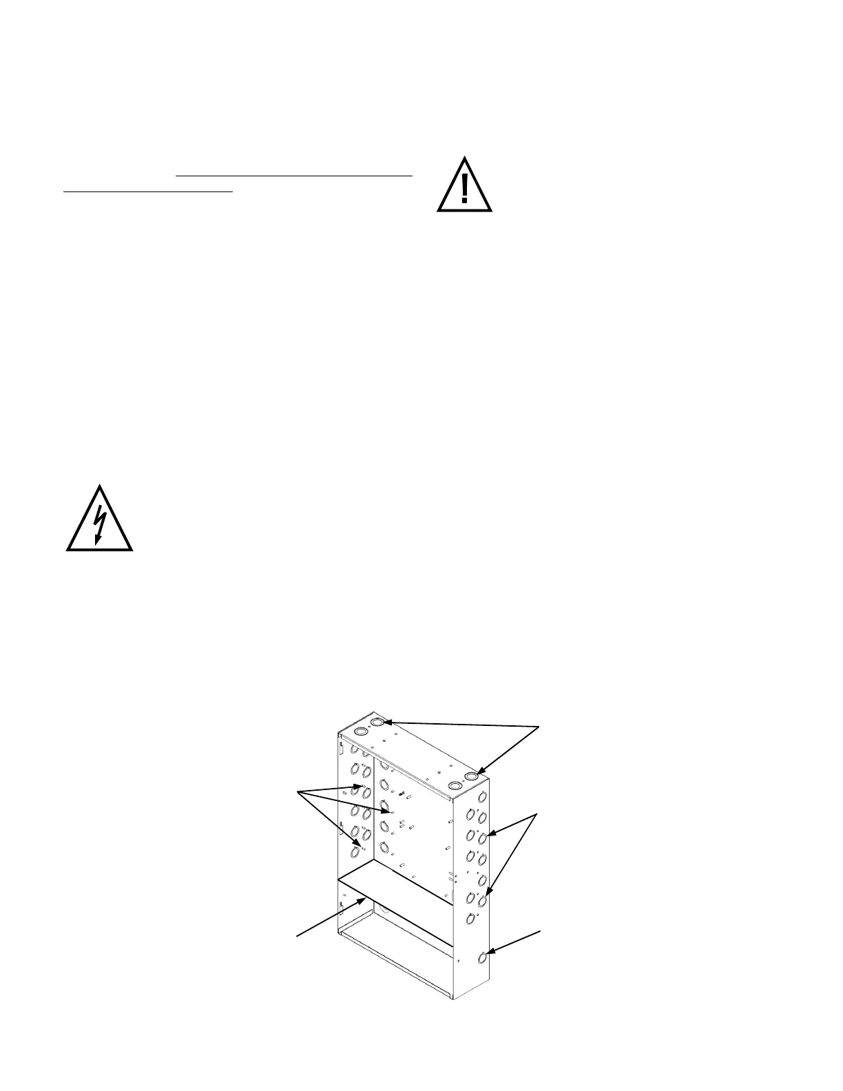
INSTALLATION
Figure 5 - Cabling Conduit Knockouts
Drain Wire and Shield
Ground Posts
Secure with Hex
6-32 Nuts Provided
Knockouts for
½" or ¾"
Conduit
Connectors
Knockouts for
½", ¾" or 1"
Conduit Connectors
All power limited wiring
to remain ABOVE the
shelf.
(
S
h
e
l
f
)
 Loading...


