Accelaterm
®
Installation and Service Manual 26
Networking
The Accelaterm can be networked with a maximum of 62
other Accelaterm units or other Continental Access access
control devices (Superterm, Turbo Superterm, Smarterm,
Miniterm and Microterm).
'485 Repeater Network Cable Requirements
Networking multiple Accelaterm panels requires 4-conductor
cable (2-two wire twisted pair), stranded, 22AWG, with
shielding, and drain wire.
For REPEAT network configurations, cable length between
EACH Accelaterm is restricted to a maximum length of 500
feet (150m).
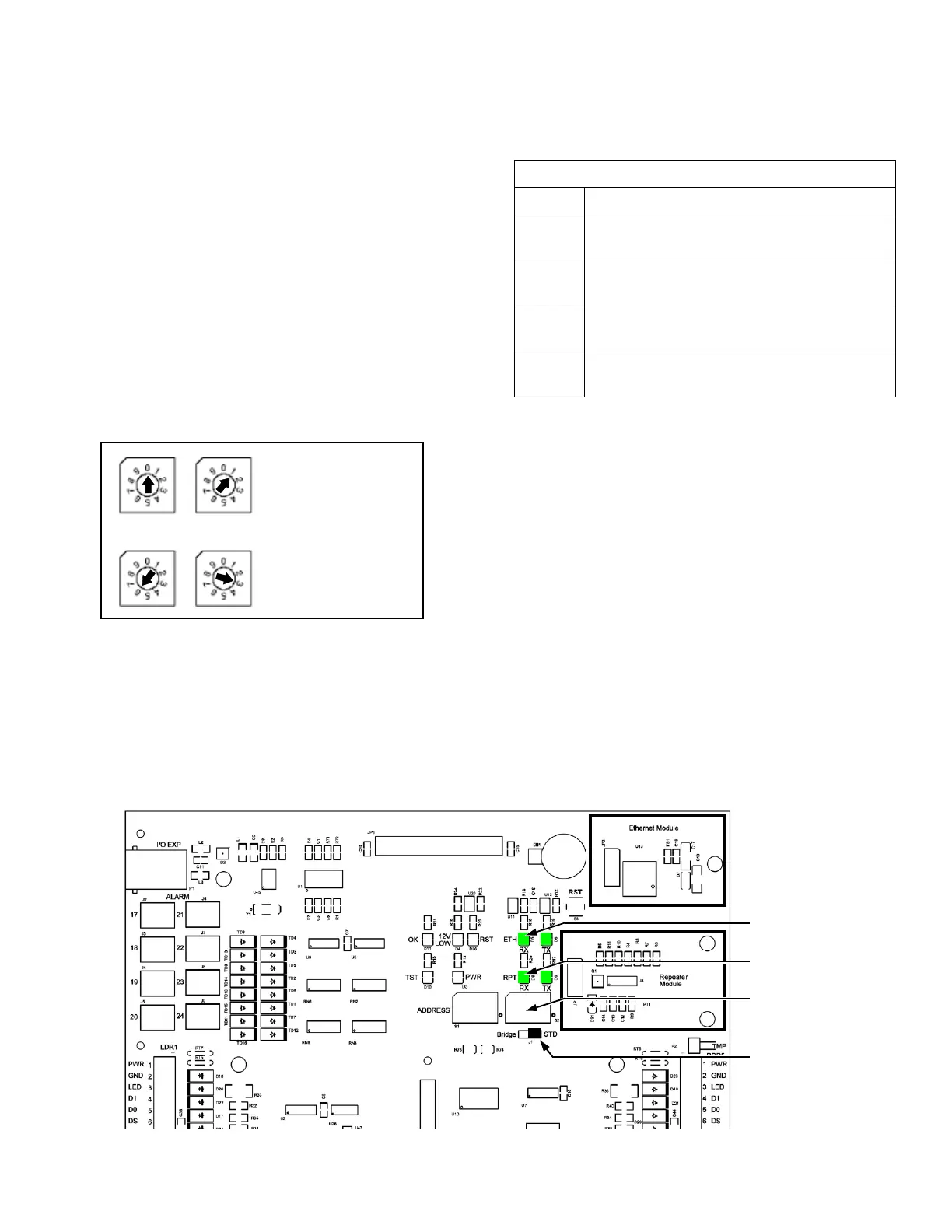
Network Address Settings
Operating the Accelaterm with a host computer, or in a net-
work, requires that each Accelaterm (or other device) have an
individual, unique address other than zero.
The BCD Rotary Switches are set with a small screwdriver.
There is a click detent for each number. The valid address
range is "01" to "63". (Address "00" is not valid).
See "Clear Memory and Force Download to Panel" on page
31.
Communication LED Functions
Communication Wiring
The Ethernet Port normally requires plenum-spec CAT 5,
CAT 5e, CAT 6 or CAT 6a cable. Maximum length allowed
in the IEEE 802.3 specification is 100 meters (305 feet).
COMMUNICATION CONNECTIONS
Figure 18 - Accelaterm Address Switch Location
ETH RX
Ethernet Port is receiving data from
the Host Computer
ETH TX
Ethernet Port is transmitting data to
the Host Computer
RPT RX
‘485 Repeater Port is receiving data
from the Host Computer
RPT TX
‘485 Repeater Port is transmitting data
to the Host Computer
Table 13 - Communication LED Functions
LED Function
Ethernet
Rx Tx LED's
Repeater
Rx Tx LED's
ADDRESS
Switches
Bridge/STD
Communication
Example: Address
“01” is set.
Example: Address
“63” is set.
Figure 17 – Setting Network Address
 Loading...


