Accelaterm
®
Installation and Service Manual 28
LED Diagnostics
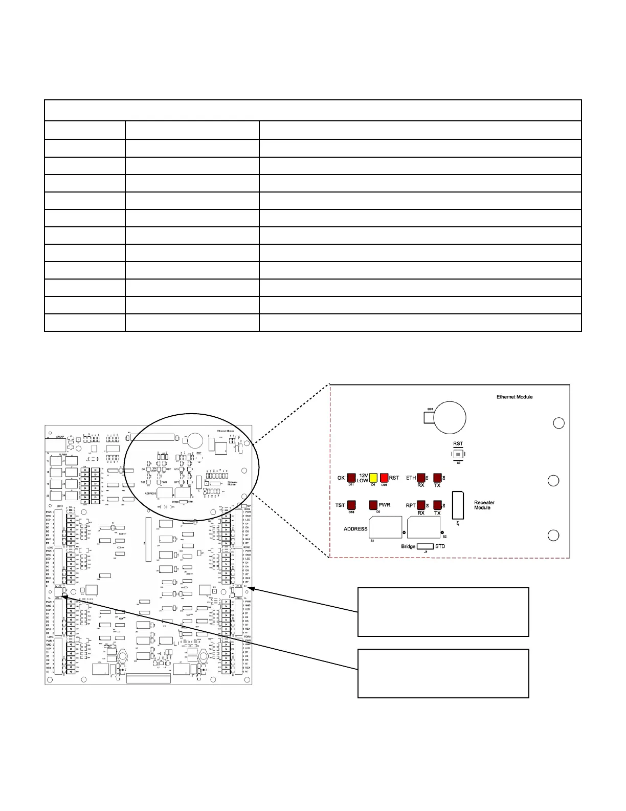
The Accelaterm circuit board uses LED's to indicate the presence of a particular voltage and EIA/TIA-232 signals. Figure 20
shows the LED position on the Accelaterm circuit board and the individual LED functions.
LED DIAGNOSTICS
Marking Function Notes
PWR Logic Power 12 Volt power and 5 Volt Regulator okay
OK Processor running okay "Heartbeat" blink signals processor, memory, etc. running
RST Reset Indicator Red during reset; steady blink indicates processor failure
12 LOW 12 Volt Power Input low Unit will soon shut down when on battery power (yellow)
TST Test Controlled by test firmware during development
ETH RX Ethernet Receive Data Ethernet Port is receiving data from the Host Computer
ETH TX Ethernet Transmit Data Ethernet Port is transmitting data to the Host Computer
RPT RX Repeater Receive Data '485 Repeater Port is receiving data from the Host Computer
RPT TX Repeater Transmit Data '485 Repeater Port is transmitting data to the Host Computer
5V (Left) 5 Volt Accessory Power Power Status monitored separately on each side
5V (Right) 5 Volt Accessory Power Power Status monitored separately on each side
Table 14 - LED Diagnostic Functions
5V 5 Volt DC Output from board, for
5 Volt Readers or Accessories.
Each side has separate Fault Protection
5V 5 Volt DC Output from board, for
5 Volt Readers or Accessories.
Each side has separate Fault Protection
Figure 20 - LED Diagnostic Functions
 Loading...