27 Accelaterm
®
Installation and Service Manual
Functions of the ‘485 Data Pair Connections
Note: A (+) is always connected to a (+), and a (-) always to a
(-). A Transmitter is always connected to a Receiver. Up-
stream cables head toward the Server; downstream cables head
away from the Server.
T+
T-
Differential
Transmitter Data
R+
R-
Differential
Receive Data
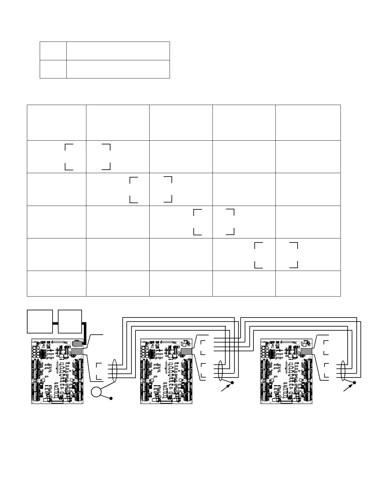
Example – Accelaterm Ethernet to ‘485 Repeater Network
ADDRESS = 01*
Ethernet and ‘485
Interfaces Installed.
Bridge
[] STD
ADDRESS = 02*
‘485 Repeater
Interface Installed.
Bridge
[] STD
ADDRESS = 03*
‘485 Repeater
Interface Installed.
Bridge
[] STD
ADDRESS = 04*
‘485 Repeater
Interface Installed.
Bridge
[] STD
ADDRESS = 05*
‘485 Repeater
Interface Installed.
Bridge
[] STD
T+
T-
R+
R-
R+
R-
T+
T-
T+
T-
R+
R-
R+
R-
T+
T-
T+
T-
R+
R-
R+
R-
T+
T-
T+
T-
R+
R-
R+
R-
T+
T-
If last unit, Downstream
Connections
left open.
UL294A compliant installation requires UL497B-Listed Surge arrestors be installed on all data lines connected to Computer Ac-
cessory Equipment. On the downstream side, Ground Loop currents are limited by the low-capacitance, high-voltage disc capaci-
tor. This connection assures compatibility with nearby Radio-Frequency equipment.
“Ethernet Only” installations may use third-party isolated USB to 485 Convertors connected to the Upstream side of the first Ac-
celaterm panel. Contact Continental Tech Support for latest data.
*Note: Address of the Accelaterm are not required to be consecutive, only that the Bridge Accelaterm be first.
Host
Computer
or Server
UL497B
Surge
Arrestor
T+
T-
R+
R-
_ _
T+
T-
R+
R-
3KV
T+
T-
R+
R-
_ _
T+
T-
R+
R-
Drain Wire connected to
Cabinet Ground Post
Bridge
OUT
STD
OUT
STD
IN
STD
OUT
STD
OUT
STD
IN
STD
IN
STD
IN
Bridge
Out
STD
Out
STD
In
T+
T-
R+
R-
_ _
T+
T-
R+
R-
Drain Wire connected to
Cabinet Ground Post
STD
Out
STD
In
COMMUNICATION CONNECTIONS
Figure 19 - Accelaterm Ethernet to ‘485 Repeater Network
 Loading...


