Accelaterm
®
Installation and Service Manual 22
EXPANSION BOARD CONNECTIONS
EXPANSION BOARD CONNECTIONS
Internally-Routed Power for
Locks 5-8 and 13-16
When the Eight Reader Expansion Board is added, relays 5-8
and 13-16 are normally used to control the locks. The control
may be with familiar dry contact power connected to each
circuit, or field wiring can be greatly simplified by routing the
lock power through the Accelaterm Relay Board.
See WI2045 for more information.
To the right of the center line on the Relay Board, find JP4
marked LOCK PWR IN [5-8] and [13-16] (not evaluated by
UL). A 9CICP2800AUXH Accessory Cable provides two
pairs of conductors for two power-limited circuits. The
power supply may be one or two UL603 or UL294 listed
units. Normally battery-backed, these may be 12VDC or 24
to 28VDC.
Considerations for use of 24VDC Equipment
• Magnetic locks drain half the current at 24V than at 12V
for the same holding force.
• Losses in the wiring resistance are ¼ that of the lower
voltage. This is significant if high-holding force locks
must be used.
• Many UL294 / UL603 power supplies offer selectable
voltage, at the same current and cost.
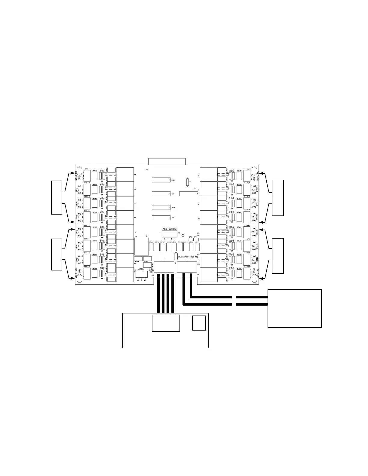
Figure 14 - CICP2800RLYBD Relay Board Layout
Relays 1-4
One or two external
UL294 / UL603 power
supplies 12/24 to 28VDC
(normally battery-
backed).
Relays 9-12
Charger / Isolator
Relays 5-8
Relays 13-16
 Loading...


