21 Accelaterm
®
Installation and Service Manual
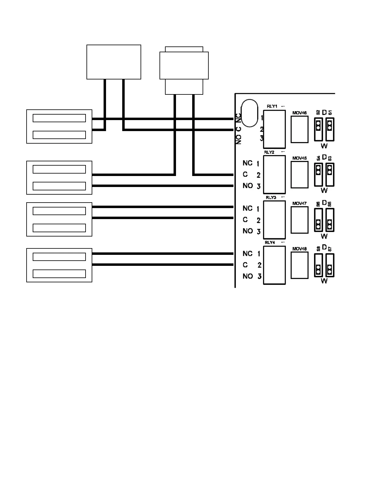
RELAY CONNECTIONS
Figure 13 - Lock Power Example
12/24 to 28 VDC
Power Supply
(–) (+)
(–) (+)
12/24 to 28 V
AC/DC
Lock Power Examples
1. Fail-Safe EM Lock
3. Fail-Safe EM Lock
4. Fail-Safe Electric Strike
Lock 1: A fail-safe electro-mechanical (EM) lock powered
by an external 12/24 to 28 VDC source. Maximum circuit
current is 2A. The configuration jumpers are set to "D" for
"Dry" contact output.
Lock 2: A fail-secure electric strike powered by a 12V or 24
to 28V, AC or DC source. Maximum circuit current is 2A.
The configuration jumpers are set to "D" for "Dry" contact
output.
Lock 3: A fail-safe EM Lock powered by the Accelaterm’s
internal battery-backed 12VDC power. Maximum recom-
mended lock current rating is 2A or less. Total system cur-
rent may not exceed 5A. Eight 600mA locks may then be
powered from the Accelaterm control panel. The configura-
tion jumpers are set to "W" for "Wet" contact output.
Lock 4: A fail-safe electric strike powered by the Ac-
celaterm’s internal battery-backed 12VDC power. Maximum
recommended lock current rating is 600mA or less. Eight
600mA locks may then be powered from the Accelaterm con-
trol panel. The configuration jumpers are set to "W" for
"Wet" contact output.
(–)
(+)
(–)
(+)
(–)
(+)
2. Fail-Secure Electric Strike
(–)
(+)
(R1)
(R2) (R3)
(R4)
 Loading...


