Accelaterm
®
Installation and Service Manual 14
Reset Button
(Press and hold
for two seconds)
Accelaterm Wiring Diagram
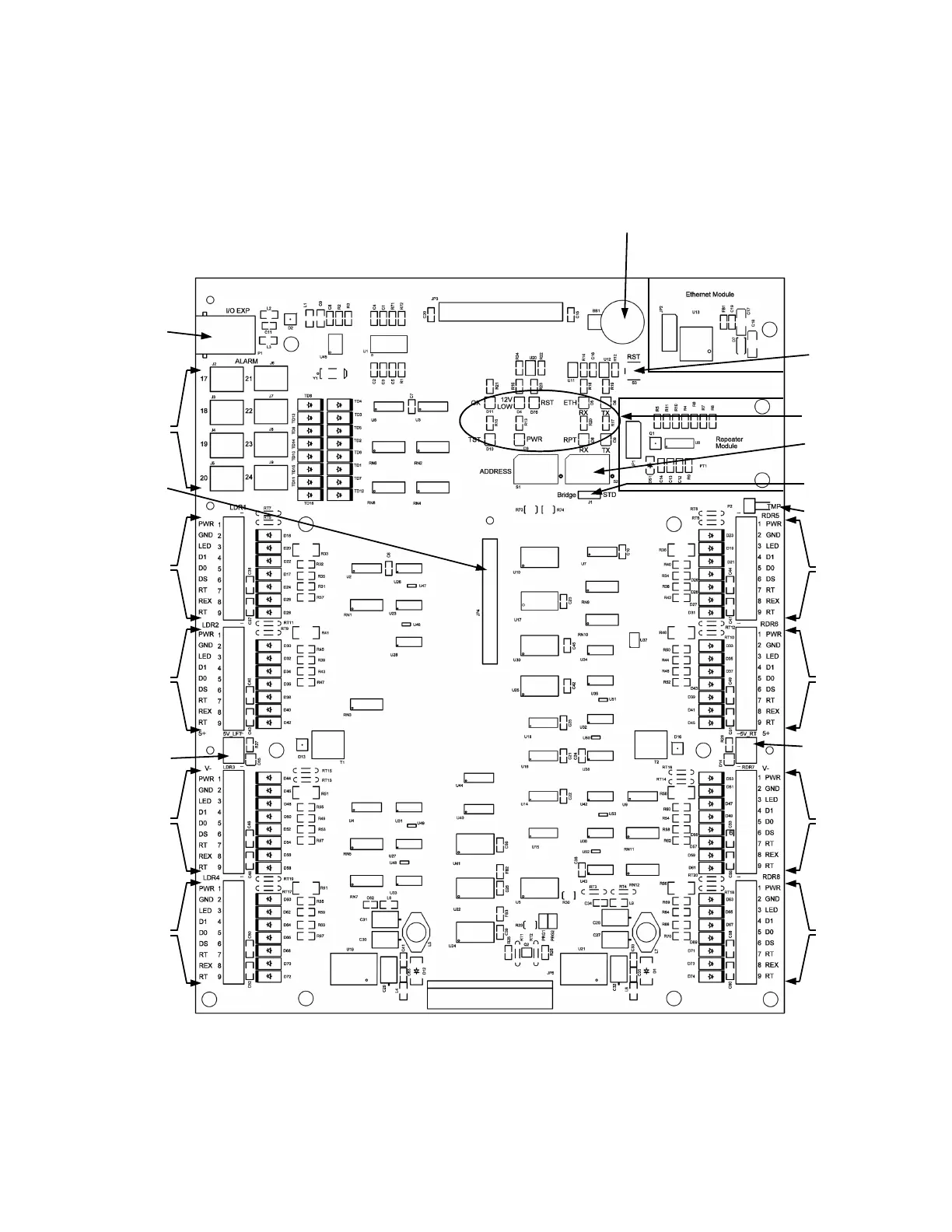
The Accelaterm circuit board (see Figure 8) provides wiring
terminal strips for external access control devices (card read-
ers, keypads, alarms, etc.).
The following descriptions in this manual reference the Ac-
celaterm main circuit board, shown below, and use cutaway
drawings to identify specific locations on the circuit board.
WIRING DIAGRAM
Figure 8 - Accelaterm Interface Circuit Board Layout
(Replaceable) Memory
Cell Holder
I2C I/O Exp
Alarm Expansion
Reader 1
Connector
Reader 2
Connector
Accessory 5
VDC Out
Reader 3
Connector
Reader 4
Connector
Status LED's
Address
Switches
Bridge/STD
Communication
Tamper In
Reader 5
Connector
Reader 6
Connector
Accessory
5 VDC Out
Reader 7
Connector
Reader 8
Connector
CICP2800EXPRDBD
8 Reader Expansion
Board connector
 Loading...


