Accelaterm
®
Installation and Service Manual 40
APPENDIX C
NOTE: Information furnished by Continental Instruments LLC is believed to be accurate and reliable. However, no responsibility is assumed by Continental Instruments LLC for its use; nor for
any infringements of other rights of third parties which may result from its use. No license is granted by implications or otherwise under any patent or patent rights of Continental Instruments LLC.
CICP2800RS485BD INSTALLATION
The CICP2800RS485BD RS-485 Repeater Board is mounted into
the Accelaterm Interface board (see the Accelaterm installation
instructions WI1989 for more information regarding the Interface
board installation).
Prior to opening the Repeater board package or
touching anything inside the control panel enclosure,
discharge any static electricity from your body or
clothing. Use a grounded wrist strap or touch an
unpainted, grounded metal object such as the metal
frame of the panel enclosure.
INSTALLATION PROCEDURE
1. Before installation, verify that the Accelaterm control panel is
working correctly.
2. Disconnect power to the system, including the battery wires.
3. Install Standoffs: The Repeater board is mounted in the top
right corner of the Accelaterm Interface board (see Fig. 2).
Screw in two metal standoffs (provided) into the two threaded
standoff holes in the Interface PC board as shown in Fig. 3.
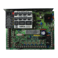
4. Align the Repeater board plug with the Interface board recep-
tacle "JP1" as shown in Fig. 4 below.
Insert the board:
With both standoffs and the plug aligned,
and the Repeater board surface parallel to the surface of the
Interface board, firmly push the Repeater board into the Ac-
celaterm Interface board.
5. As shown in Fig. 5, insert two small screws into the two metal
threaded standoffs noted in Fig. 3 and tighten to secure the
Repeater board. Do not over-tighten the screws.
9. Re-connect power to the system, including the battery wires.
Fig. 3: Insert two metal standoffs into threaded holes.
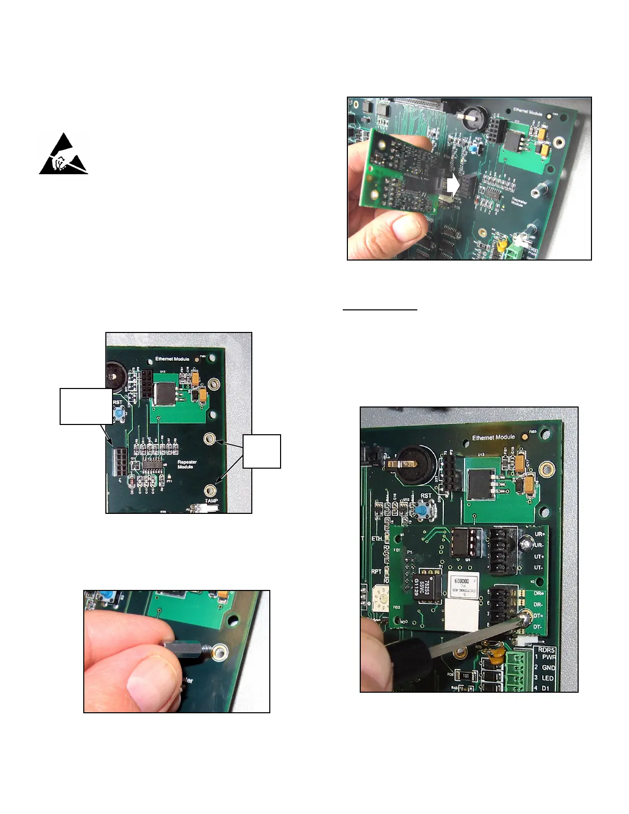
Fig. 2: Repeater Board Installation location, and
Standoff Holes. Receptacle "JP1" also shown.
Threaded
Standoff
Holes
Interface board
receptacle
"JP1"
Fig. 4: Align the Repeater board plug with Interface board receptacle "JP1".
Fig. 5: Secure the Repeater board with two screws.
 Loading...