W415-1347 / A / 03.19.15
41
EN
8.0 WIRING DIAGRAM / ELECTRICAL INFORMATION
!
WARNING
DO NOT USE THIS APPLIANCE IF ANY PART HAS BEEN UNDER WATER. CALL A QUALIFIED
SERVICE TECHNICIAN IMMEDIATELY TO HAVE THE APPLIANCE INSPECTED FOR DAMAGE TO THE
ELECTRICAL CIRCUIT.
RISK OF ELECTRICAL SHOCK OR EXPLOSION. DO NOT WIRE 110V TO THE VALVE OR TO THE
APPLIANCE WALL SWITCH. INCORRECT WIRING WILL DAMAGE CONTROLS.
ALL WIRING SHOULD BE DONE BY A QUALIFIED ELECTRICIAN AND SHALL BE IN COMPLIANCE
WITH LOCAL CODES. IN THE ABSENCE OF LOCAL CODES, USE THE CURRENT CSA22.1 CANADIAN
ELECTRIC CODE IN CANADA OR THE CURRENT NATIONAL ELECTRIC CODE ANSI/NFPA NO. 70 IN
THE UNITED STATES.
ALWAYS LIGHT THE PILOT WHETHER FOR THE FIRST TIME OR IF THE GAS SUPPLY HAS RAN OUT,
WITH THE GLASS DOOR OPENED OR REMOVED.
69.2
8.1 WIRING REQUIREMENTS
A. This appliance must be electrically connected and grounded in accordance with local codes. In the
absence of local codes, use the current CSA C22.1 CANADIAN ELECTRICAL CODE in Canada or the
ANSI/NFPA 70-1996 NATIONAL ELECTRICAL CODE in the United States.
B. Low voltage and 110 VAC voltage cannot be shared within the same wall box.
C. Wire the appliance junction box to 110 VAC for proper operation of the appliance.
D. Refer to “WIRING DIAGRAM” section.
E. This appliance is equipped with an electronic control valve which operates on a 3 volt system.
F. Plug the 3 volt AC transformer into the appliance junction box to supply power to the appliance
and install two “D” cell batteries (not included) into the battery tray before use (only required if the
appliance is to operate during a power failure).
8.2 OPTIONAL ACCESSORIES REQUIREMENTS
A. This appliance may be used with a wall switch and/or a remote control
B. Wiring for optional Wolf Steel approved accessories should be done now to avoid reconstruction.
Follow instructions that come with those accessories.
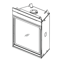
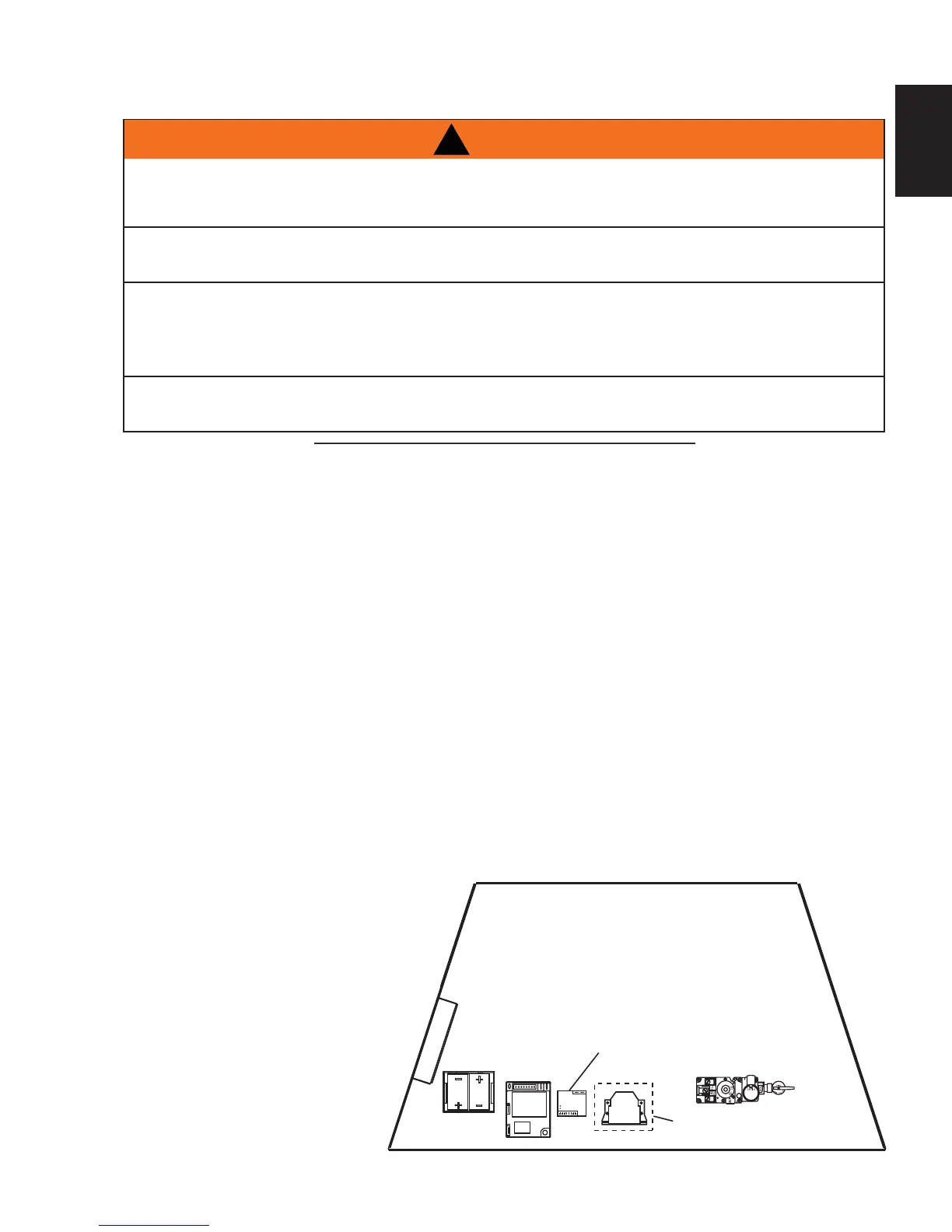
C. The Battery Tray, IPI Control Module, and Remote Control Receiver can be accessed through the air
space between the fi rebox front and the lower-front fi nishing cover panel.
D. The Battery Tray, IPI Control Module, Remote Control Receiver must be secured using Velcro to the
inside of the lower cover panel.
OPTIONAL REMOTE CONTROL RECEIVER
LOCATION
E. Optional remote control receiver
locations as shown in illustration
below.
JUNCTION
BOX
BATTERY
TRAY
IPI MODULE
GAS VALVE
BATTERY
RELAY
REMOTE CONTROL
RECEIVER LOCATIONS