W415-1347 / A / 03.19.15
43
EN
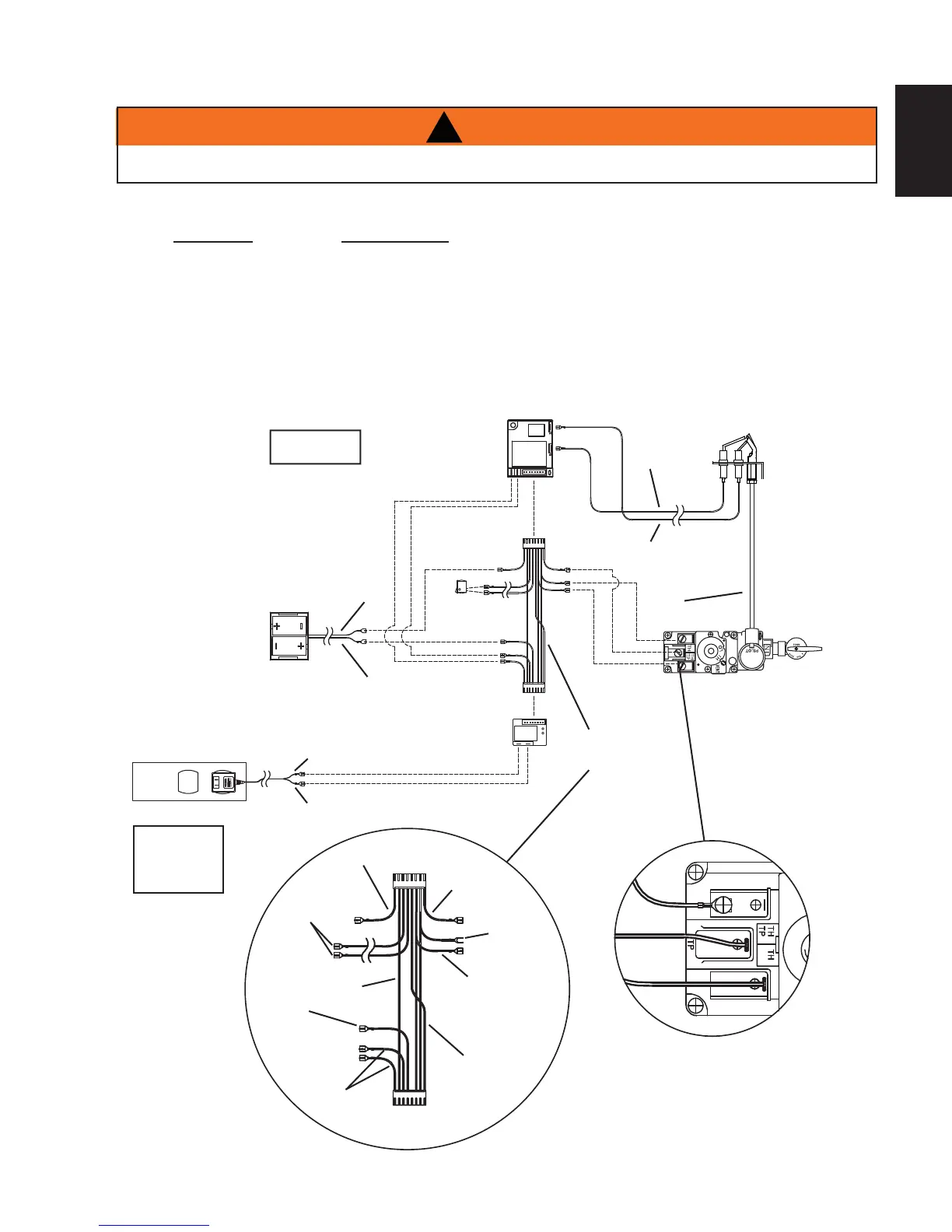
BATTERY
HOLDER
GAS VALVE
PILOT
ASSEMBLY
IGNITION
MODULE
PILOT
G
AS LINE
(I)
(S)
AC ADAPTOR
BATTERY
RELAY
RED
WIRE
HARNESS
NOTE: WIRE TAGS
ARE BRACKETED
(-)
(+)
(TH)
(THTP)
(TP)
MODULE
P
LUG
RELAY
PLUG
MAIN BURNER SWITCH
(20’ REMOTE SWITCH
WIRE SUPPLIED)
BLACK
JUNCTION
BOX
NOTE: P LUG THE
3 VOLT AC ADAPTOR
INTO THE APPLIANCE
JUNCTION BOX TO
SUPPLY POWER TO
THE UNIT.
BLACK
BLACK
BLACK
RED
ORANGE X2
G
REEN X2
B
LUE
YELLOW
MAIN BURNER SWITCH
BROWN
(SWI)
B
LACK
ORANGE
GREEN
ORANGE [THROUGH
INDEPENDENT
CONDUIT]
YELLO [THROUGH
GAS LINE
CONDUIT]
RED
BLACK
A wall switch must be installed in a convenient location for the burner operation.
The recommended maximum lead length depends on the wire size:
WIRE SIZE MAX. LENGTH
14 gauge 100 feet (30m)
16 gauge 60 feet (18m)
18 gauge 40 feet (12m)
A 20’ (6m) length of wire is connected to the main burner switch leads. Connect this wire to the wall switch.
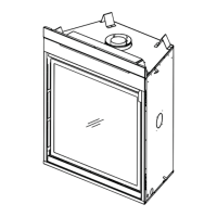
However if a greater length is required route 2-strand (solid core) wire through the electrical hole located at the
bottom left side of the appliance.
8.4 WIRING DIAGRAM
!
WARNING
DO NOT WIRE 100 VOLTS TO THE VALVE OR WALL SWTICH.