General Information 1-5
1.8 Front Panel
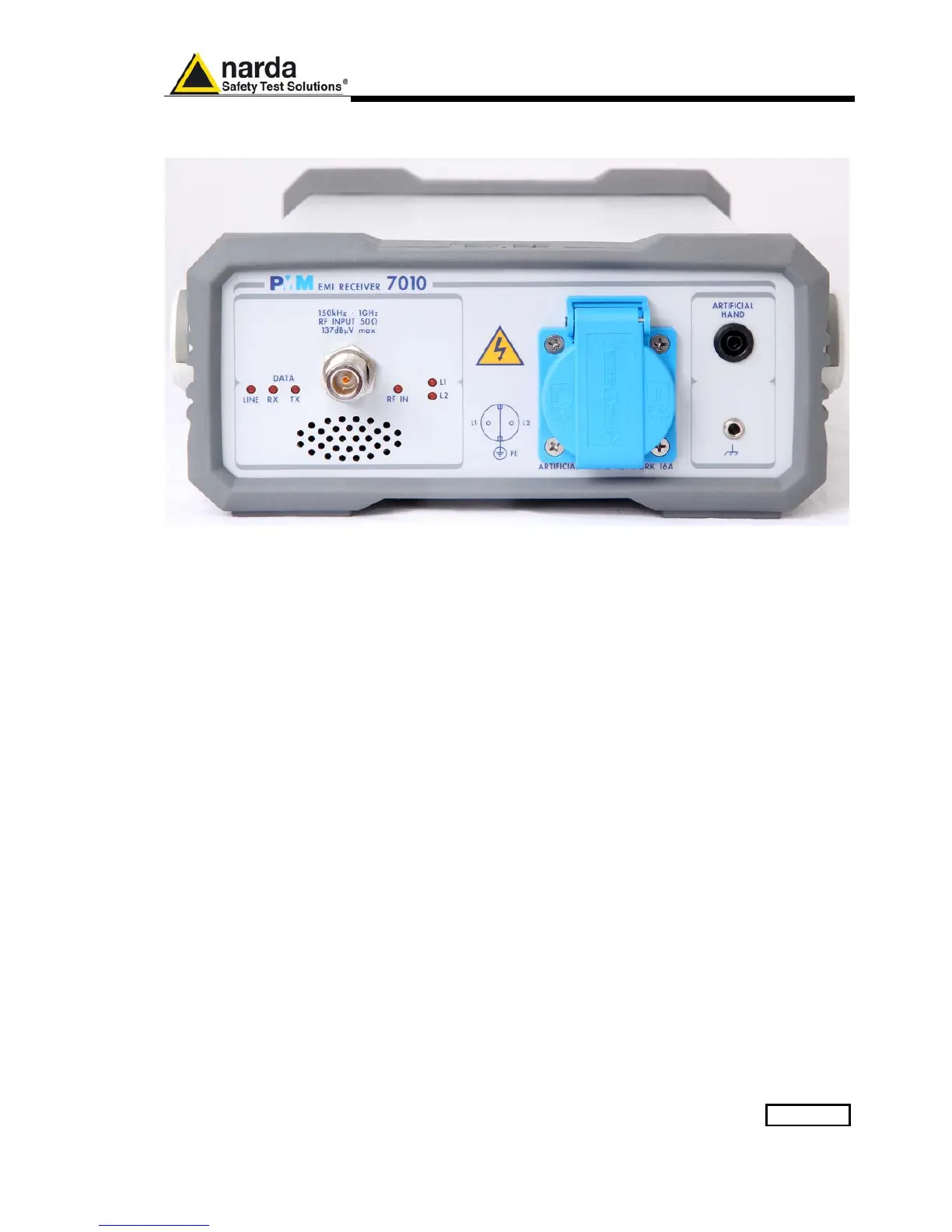
Fig. 1-1 7010 Option 00 Front Panel
Legend from left to right:
- Line Power led
- DATA RX-TX Leds which show the serial communication status
- RF INPUT N female RF Input connector
- RF IN This led indicates if the signal source is from the internal LISN or from the N connector
- L1 – L2 These two leds indicate the line of the internal LISN under investigation.
- Artificial Mains Network 16A It is the mains socket where the supply of the EUT must be connected
to measure its conducted emissions.
The line comes through the internal LISN and is capable of handling
16A of max current.
- Artificial Hand standard 4 mm socket
- Earth ground connector