EasyManua.ls Logo

NARDA PMM 9010F - User Manual

Default Icon
284 pages
Print Icon
To Next Page IconTo Next Page
Loading...
NARDA
Safety
Test
Solutions
S.r.l. Socio Unico
Sales & Support:
Via Leonardo da Vinci, 21/23
20090 Segrate (MI) -
ITALY
Tel.: +39 02 2699871
Fax: +39 02 26998700
Manufacturing Plant:
Via Benessea, 29/B
17035 Cisano sul Neva (SV)
Tel.: +39 0182 58641
Fax: +39 0182 586400
http://www.narda-sts.it
SERIAL NUMBER OF THE INSTRUMENT
You can find the Serial Number on the rear panel of the instrument.
Serial Number is in the form: 0000X00000.
The first four digits and the letter are the Serial Number prefix, the last five digits are the
Serial Number suffix. The prefix is the same for identical instruments, it changes only
when a configuration change is made to the instrument.
The suffix is different for each instrument.
Document 9010EN-81037-2.57 - Copyright © NARDA 2018
User’s Manual
PMM 9010
EMI CISPR RECEIVER
10 Hz ÷ 30 MHz
Including description of:
- PMM 9010F Fast EMI CISPR Receiver
10 Hz ÷ 30 MHz Full compliance
- PMM 9010/03P EMI CISPR Receiver
10 Hz ÷ 30 MHz Full compliance
30 MHz ÷ 300 MHz Compliance (PRF 10Hz)
- PMM 9010/30P EMI CISPR Receiver
10 Hz ÷ 30 MHz Full compliance
30 MHz ÷ 3 GHz Pre compliance
- PMM 9010/60P EMI CISPR Receiver
10 Hz ÷ 30 MHz Full compliance
30 MHz ÷ 6 GHz Pre compliance
- PMM 9030 EMI CISPR Receiver
Full compliance extension (up to 3 GHz)
- PMM 9060 EMI CISPR Receiver
Full compliance extension (up to 6 GHz)
- PMM 9180 EMI CISPR Receiver
Full compliance extension (up to 18 GHz)
- PMM 9010/Click Analyzer option

Table of Contents

Question and Answer IconNeed help?

Do you have a question about the NARDA PMM 9010F and is the answer not in the manual?

NARDA PMM 9010F Specifications

General IconGeneral
BrandNARDA
ModelPMM 9010F
CategoryReceiver
LanguageEnglish

Summary

General Safety Recommendations

Electrical and Safety Symbols

Explains standard electrical and safety symbols used in the manual.

1 General Information

1.3 Introduction to PMM 9010

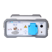
Introduces the PMM 9010 EMI receiver and its capabilities.

1.7 Main Specifications

Details the performance specifications of the PMM 9010 receiver under standard conditions.

1.12 Emission Measurement

Discusses EMI generation and the role of standards in emission measurements.

2 Installation

2.1 Introduction

Provides an overview of the installation process for the PMM 9010.

2.4 Preparation for Use

Emphasizes the importance of a proper earth ground connection.

2.10 Hardware Installation

Guides on the initial power-on and boot sequence of the PMM 9010.

2.11 Using an Artificial Mains Network (AMN or LISN)

Explains how to use LISNs for conducted interference measurements.

3 Setup and Panel Instructions

3.1 Introduction

Explains how to enter the Setup window for global parameter configuration.

3.3 Autocal

Explains the automatic self-calibration process using the tracking generator.

4 Sweep Mode Operating Instructions

4.1 Introduction

Explains the Sweep mode as a scanning EMI receiver function.

4.2.2.3 Smart Detector

Describes the Smart Detector function for reducing test time.

5 Analyzer Mode Operating Instructions

6 Manual Mode Operating Instructions

7 Applications

7.1 Measuring the EMI Voltage

Describes EMI voltage measurements using coupling networks or transducers.

7.1.4 Guidance on a preliminary Measuring Procedure

Offers a step-by-step example of a conducted test procedure.

8 Updating Firmware and Activation Code Utility

9 PMM 9010;03 P EMI CISPR Receiver

9.7 PMM 9010;03 P Main Specifications

Details performance specifications for the PMM 9010/03P EMI receiver.

9.10 PMM 9010;30 P Main Specifications

Details performance specifications for the PMM 9010/30P EMI receiver.

9.13 PMM 9010;60 P Main Specifications

Details performance specifications for the PMM 9010/60P EMI receiver.

10 Click Mode Operating Instructions (Option)

10.2 Click Mode Activation Procedure

Guides on enabling the Click Mode using the 9010 Set code Utility.

10.3 Enter the Click Mode

Explains how to enter the Click Mode and its initial window.

10.4 Introduction to the discontinuous disturbance (click) measurement

Explains the concept and standards for click measurement.

10.4.1 Determination of the click rate

Details the process of determining the click rate N.

10.7 Setup

Details the complex setup parameters for the discontinuous disturbance test.

11 PMM 9030;9060;9180 EMI CISPR Receiver Extension, 30 MHz - 3;6;18 GHz (Option)

11.5 PMM 9030 Main Specifications

Details performance specifications for the PMM 9030 receiver.

11.7 PMM 9060 Main Specifications

Details performance specifications for the PMM 9060 receiver.

11.9 PMM 9180 Main Specifications

Details performance specifications for the PMM 9180 receiver.

11.14 Installation

Covers initial inspection, packing, preparation, battery, environment, service, cleaning, ventilation, and hardware installation.

12 PMM 9010-RMA Rack Mount Adapter for Rack 19” (Option)

12.4 PMM 9010-RMA Main Specifications

Details the technical specifications for the PMM 9010-RMA Rack Mount Adapter.

12.11 Installing the PMM 9010-RMA

Provides step-by-step instructions for installing the adapter into a rack.

13 APD Mode Operating Instructions (Amplitude Probability Distribution)

13.2 Pre-conditions and Settings

Covers pre-conditions and settings required for APD measurements.

13.3 Setup

Details the setup parameters for APD measurements, including limits and frequencies.

14 Remote control

14.5 PMM 9010 COMMANDs

Lists the commands for controlling PMM 9010 operating modes.

15 - 9010 F Fast

15.1.1 Principle of operation

Explains the real-time, gapless receiver operation based on FFT.

15.1.5 Main Specifications

Details the performance specifications of the PMM 9010F receiver.

15.2 Sweep Mode

Explains the Sweep mode as a scanning EMI receiver function.

15.3 Analyzer Mode

Introduces Analyzer mode for spectrum analysis.

Annex - A RMS-AVG and C-AVG Detectors

A-A.5.2 Smart Detector

Describes the Smart Detector function for reducing test time.

Annex - C Click4 E Four Channels Click Meter Option

A-C.2 Installation Procedures

Covers inspection, packing, preparation, mains supply, battery charging, and environment.

A-C.3 Click Mode menu

Explains the commands and LED indicators for the Click Mode function.

A-C.5.1 Smart Measure

Highlights the Smart Measure feature for time saving in click measurements.

Related product manuals