9-12 General Information
9.14 PMM 9010/60P
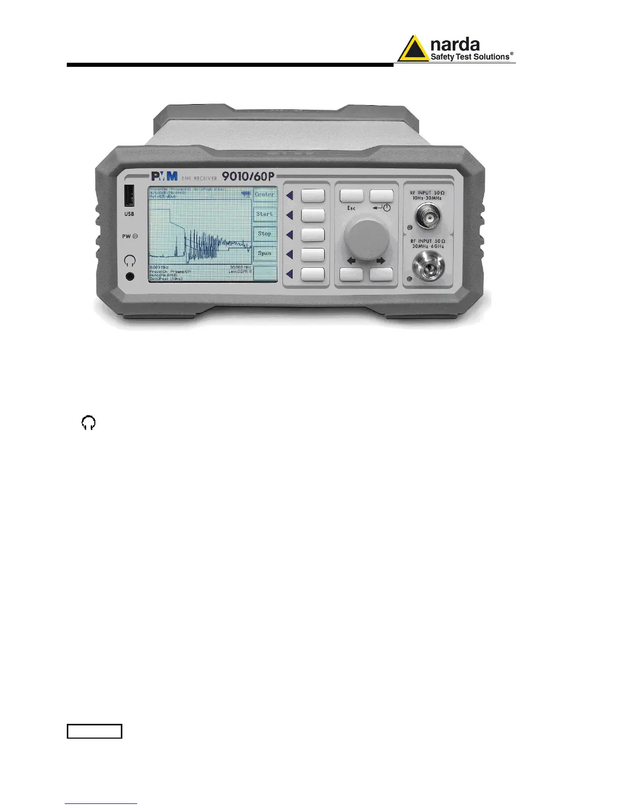
Front Panel
Fig. 9-7 Front Panel
Legend from left to right:
- USB USB 2.0 connection port (future implementation only)
- PW Power led
Indicates the power status
-
Earphone connector
To listen to the demodulated signals
- DISPLAY Main display
To graphically show the instrument status
- User keys 5 command keys
To select the various available functions
- Controls Rotary Knob, Left and Right (decrease / increase) Arrow Keys; Esc; Enter/Switch Key
The Rotary Knob and the Arrows Keys can be used to increase and decrease the
setting values; the Esc key allows to return to the previous status/display;
the Enter/switch key is used to confirm a set value and to switch On and Off
the equipment
- Input connectors
Input from 10 Hz ÷ 30 MHz (BNC connector)
Input from 30 MHz ÷ 6 GHz (N connector)
- “RF Input 50Ω 10 Hz ÷ 30 MHz” Led
Indicates when the Receiver Input is active
- “RF Input 50Ω 30 MHz ÷ 6 GHz” led
Indicates when the Receiver Input is active