LISN with PMM 9010 A-D-1
Annex - D
Procedure to measure the insertion
loss of a LISN with a
PMM 9010 Receiver
All the tests are done under the responsibility of the Operator who is
carrying them out.
A-D.1 Introduction
This paragraph provides information concerning how to test and measure
the Insertion Loss of any Line Impedance Stabilization Network (LISN).
Taking this as a guide, in a similar way other instruments or circuits can be
checked or calibrated.
A-D.2 Operation
The purpose of this procedure is to show how to operate the PMM 9010
receiver in order to measure the transfer function of a LISN in the CISPR
16-1-2 conducted frequency range from 9 kHz to 30 MHz.
It can be useful, for example, to make periodic tests as well as to check
new instruments or make comparisons.
A-D.3 Test setup
To carry out the test the following parts are required:
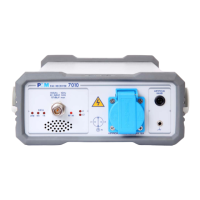
• EMI Receiver PMM 9010 with its User’s Manual
• #2 RF Coaxial BNC-BNC Cables
• LISN under test
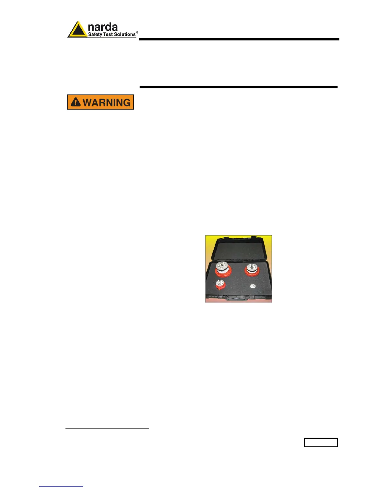
• Special AC-Plug to BNC adapters (provided for the most diffused AC
single-phase Schuko and Three-Phase sockets, see following A-D-13
section for further references)
A-D.4 Settings
Before starting the test, it is necessary to set the PMM 9010 receiver
according to the following list.
Refer to the User’s Manual to find how to operate the receiver in order to
set it properly.
• RF OUTPUT = ON
• TG = ON (default)
• OUTPUT LEVEL = 90.0 dBμV (default)
• MODE = SWEEP
• PRESELECTOR = ON (default)
• PREAMPLIFIER = OFF (default)
• REF. LEVEL = 110 dBμV
• DYNAMIC RANGE = 80 dB
• ATTENUATOR = AUTO (default)
• DETECTOR = AVG
• HOLD TIME = MINIMUM (default)
• FREQUENCY = A+B (default)
Document 9010EN-81037-2.57 - © NARDA 2018