7-2 | ni.com
Chapter 7 Digital Routing, Clock Generation, and Synchronization
Clock Routing
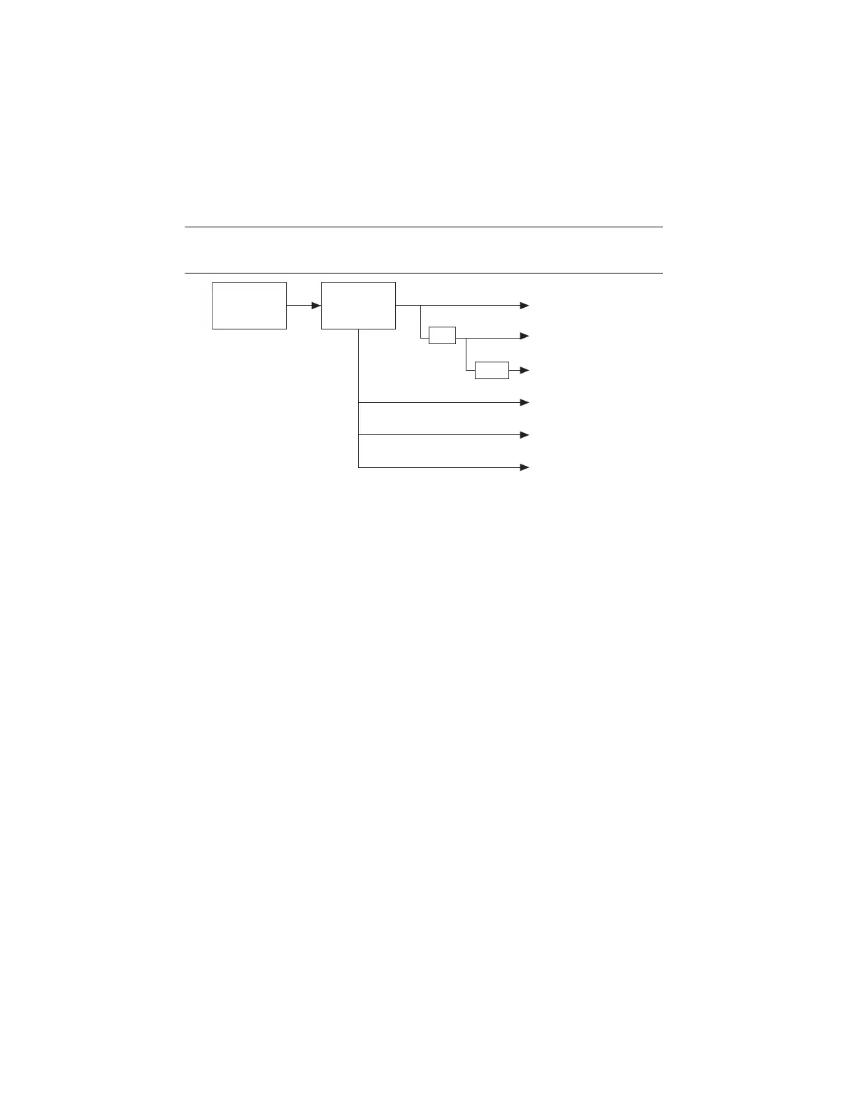
Figure 7-1 shows the clock routing circuitry of the cDAQ chassis.
Figure 7-1. Clock Routing Circuitry
80 MHz Timebase
You can use the 80 MHz Timebase as the Source input to the 32-bit general-purpose
counter/timers. The 80 MHz Timebase can be generated from the onboard oscillator.
20 MHz and 100 kHz Timebases
The 20 MHz and 100 kHz Timebases can be used to generate many of the analog input and
analog output timing signals. They can function as the Source input to the 32-bit general-purpose
counter/timers. The 20 MHz and 100 kHz Timebases are generated by dividing down the
80 MHz Timebase, as shown in Figure 7-1.
13.1072 MHz, 12.8 MHz, and 10 MHz Timebases
The 13.1072 MHz, 12.8 MHz, and 10 MHz Timebases can be used to generate many of the
analog input and analog output timing signals. They can function as the Source input to the
32-bit general-purpose counter/timers. The 13.1072 MHz, 12.8 MHz, and 10 MHz Timebases
are generated directly from the onboard clock generator.
÷
4
÷
200
80 MHz Timebase
100 kHz Time
base
20 MHz Timebase
13.1072 MHz Timebase
10 MHz Timebase
12.8 MHz Timebase
Clock
Generator
Onboard
100 MHz
Oscillator
Artisan Technology Group - Quality Instrumentation ... Guaranteed | (888) 88-SOURCE | www.artisantg.com

 Loading...