1-28 | ni.com
Chapter 1 Getting Started with the cDAQ Chassis
4. Use a #2 Phillips screwdriver to tighten the captive screw on the end bracket.
5. Repeat steps 2 and 3 to attach the other end bracket to the other end of the chassis.
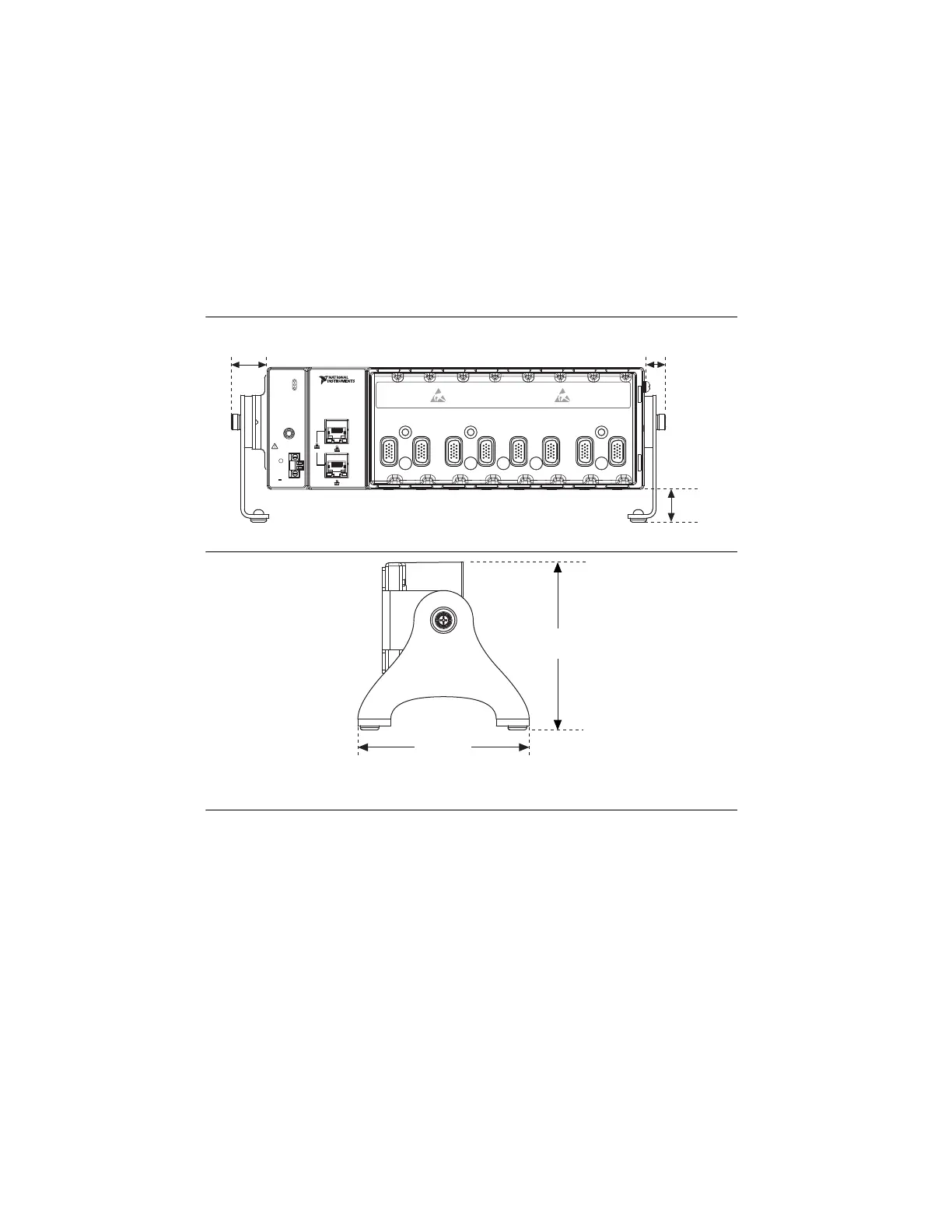
The following figures show the desktop mounting kit dimensions.
Figure 1-26. Desktop Mounting Front Dimensions (cDAQ-9189 Shown)
Figure 1-27. Desktop Mounting Side Dimensions
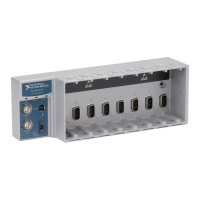
cDAQ Chassis Features
The cDAQ chassis features a chassis grounding screw, LEDs, reset button, two Ethernet ports,
power connector, and one PFI SMB connector. Refer to Figure 1-1 or 1-2 for locations of the
cDAQ chassis features.
LEDs
The statuses for the POWER, STATUS, and ACTIVE LED indicators on the cDAQ chassis are
listed in Table 1-3.
LINK/
ACT
10/100/
1000
1
2
LINK/
ACT
10/100/
1000
NI CompactDAQ
NI cDAQ-9189
POWER
STATUS
ACTIVE
PFI 0
RESET
INPUT
DO NOT SEPARATE
CONNECTORS
WHEN ENERGIZED
IN HAZARDOUS
LOCATIONS
9-30 V
16 W MAX
SYNC
V
C
C
V
12345678
17.2 mm
(0.68 in.)
39.1 mm
(1.54 in.)
22.9 mm
(1.14 in.)
127.0 mm
(5.00 in.)
130.0 mm
(5.12 in.)
Artisan Technology Group - Quality Instrumentation ... Guaranteed | (888) 88-SOURCE | www.artisantg.com