1-6 | ni.com
Chapter 1 Getting Started with the SCB-68A
10. Connect the SCB-68A(s) to the DAQ device using the appropriate cable(s) for your device.
For a complete list of cabling options for supported devices, refer to the KnowledgeBase
document, Compatible Devices and Cabling for the NI SCB-68/SCB-68A Terminal Block.
To access this document, go to
ni.com/info and enter the Info Code scb68acables.
11. Launch Measurement & Automation Explorer (MAX), in the left panel, expand Devices
and Interfaces to confirm that your DAQ device is recognized, and then configure your
device settings.
12. (Optional) To take measurements with an MIO DAQ device, configure the SCB-68A as an
accessory for a DAQ device by completing the following steps.
a. In MAX, right-click your DAQ device and select Configure.
b. On the Accessory tab, select SCB-68A from the pull-down menu and select
Configure.
1
c. In the Accessory Configuration window, enable or disable the temperature reference
sensor and click OK.
d. Click OK.
For more information about configuring the SCB-68A for a DAQ device, refer to the
Measurement & Automation Explorer Help for NI-DAQmx.
13. Test specific device functionality. Run a Test Panel in MAX by right-clicking your DAQ
device and selecting Test Panels. Click Start to test the device functions.
When you have finished using the SCB-68A, power off any external signals connected to the
SCB-68A before you power off your computer.
Using the SCB-68A in Direct Feedthrough Mode
Devices without analog input functionality, as well as R Series, AO Series, and DIO/TIO Series
devices, must use direct feedthrough mode. Move the switches to the direct feedthrough mode
switch setting shown in Table 1-1.
1
MAX 5.3 or later. You can select SCB-68 as your accessory in earlier versions of MAX.
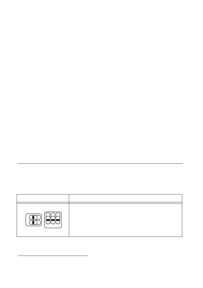
Table 1-1. Direct Feedthrough Switch Setting
Switch Setting Description
Direct feedthrough mode—Move switches S1.1, S1.2, S2.1,
S2.2, and S2.3 to the positions shown at left. In this mode:
• All 68 signals from the device connect directly to
screw terminals.
Refer to Figure 1-3 for a detailed diagram.

 Loading...
