© National Instruments | 2-27
NI SCB-68A User Manual
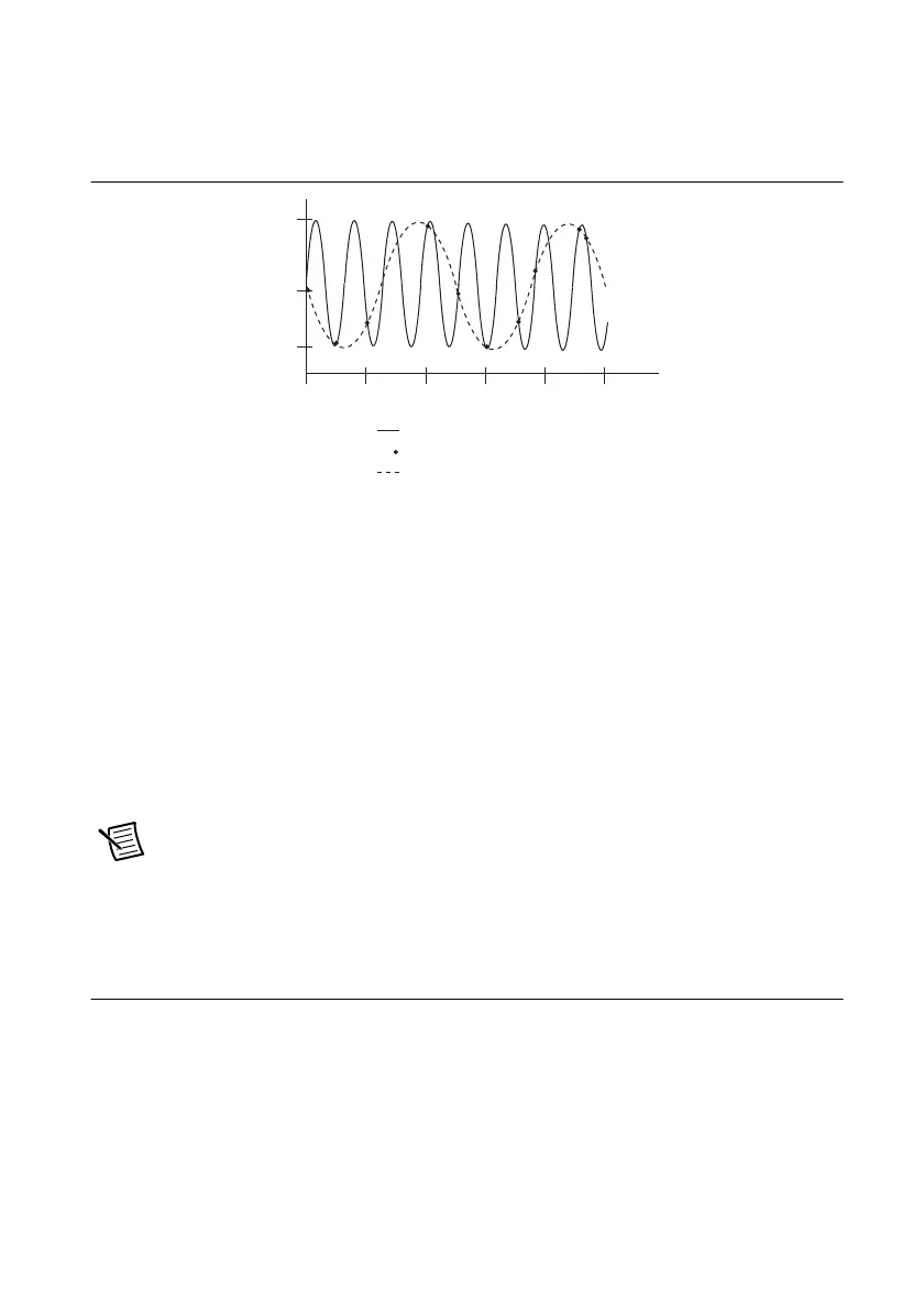
• Antialiasing filtering—Aliasing causes high-frequency signal components to appear as a
low-frequency signal, as Figure 2-24 shows.
Figure 2-24. Aliasing of a High-Frequency Signal
The solid line depicts a high-frequency signal being sampled at the indicated points. When
these points are connected to reconstruct the waveform, as shown by the dotted line, the
signal appears to have a lower frequency. Any signal with a frequency greater than one-half
of its sample rate is aliased and incorrectly analyzed as having a frequency below one-half
the sample rate. This limiting frequency of one-half the sample rate is called the Nyquist
frequency.
To prevent aliasing, remove all signal components with frequencies greater than the
Nyquist frequency from input signals before those signals are sampled. Once a data sample
is aliased, it is impossible to accurately reconstruct the original signal.
To design a lowpass filter that attenuates signal components with a frequency higher than
half of the Nyquist frequency, substitute the half Nyquist value for the f
c
value in
Equation 2-3.
Note (NI 6115/6120/6289 Devices Only) Some devices, such as the
NI 6115/6120/6289, provide filters and may not need antialiasing filters
implemented at the SCB-68A terminal block. Refer to your device documentation for
more information.
Highpass Filtering
Highpass filters highly or completely attenuate signals with frequencies below the cut-off
frequency, or low-frequency stopband signals. Highpass filters do not attenuate signals with
frequencies above the cut-off frequency, or high-frequency passband signals.
The cut-off frequency, f
c
, is defined as the frequency below which the gain drops 3 dB.
Figure 2-25 shows how an ideal filter causes the gain to drop to zero for all frequencies less than
f
c
. Thus, f
c
does not pass through the filter to its output.
2468 100
1
–1
Input Signal
Sampled Points
Reconstructed Signal
 Loading...

