EasyManuals Logo
Home>National Instruments>Cables and connectors>SCB-68A

National Instruments SCB-68A User Manual

National Instruments SCB-68A
91 pages
To Next Page IconTo Next Page
To Previous Page IconTo Previous Page
Page #80 background imageLoading...
Page #80 background image
4-10 | ni.com
Chapter 4 PFI 0 and Digital Input Measurements
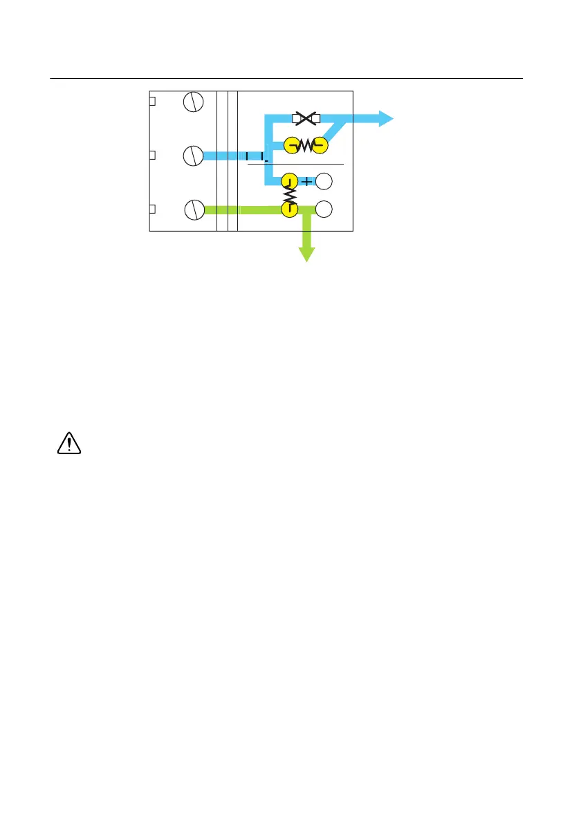
Figure 4-13. SCB-68A Circuit Diagram for Digital Input Attenuation
Use positions A and B for PFI 0, and determine the gain according to Equation 4-5:
(4-5)
Digital Input Voltage Dividers
If you use the V
in
voltage of Figure 4-12 to feed TTL signals, you must calculate V
in
so that the
voltage drop on R
2
does not exceed 5 V.
Caution A voltage drop exceeding 5 V on R
2
can damage the internal circuitry of
the DAQ device. NI is not liable for any device damage resulting from improper use
of the SCB-68A and the DAQ device.
45
11
44
SC10
A
+
B
11
+
44
PFI 0
D GND
G
B
BA+()
------------------=

Table of Contents

Questions and Answers:

Question and Answer IconNeed help?

Do you have a question about the National Instruments SCB-68A and is the answer not in the manual?

National Instruments SCB-68A Specifications

General IconGeneral
BrandNational Instruments
ModelSCB-68A
CategoryCables and connectors
LanguageEnglish

Related product manuals