© National Instruments | 2-25
NI SCB-68A User Manual
Choose a capacitor that has the following suggested characteristics:
• AXL or RDL package
• Tolerance of 20%
• Maximum voltage of at least 25 V
Adding Components for Lowpass Filters on Analog
Input Signals
Using the circuit shown in Figure 2-21, you can use a two-component circuit to build a simple
RC filter with analog input. You can build a lowpass filter for the following analog input modes:
• Differential analog input lowpass filter—To build a differential lowpass filter, refer to
Figure 2-22. Add the resistor to position F and the capacitor to position E. Refer to
Table 2-1 for component positions for all analog input channels.
The SCB-68A ships with a surface mount 0 Ω resistor in the F position. You must remove
the resistor to use the position.
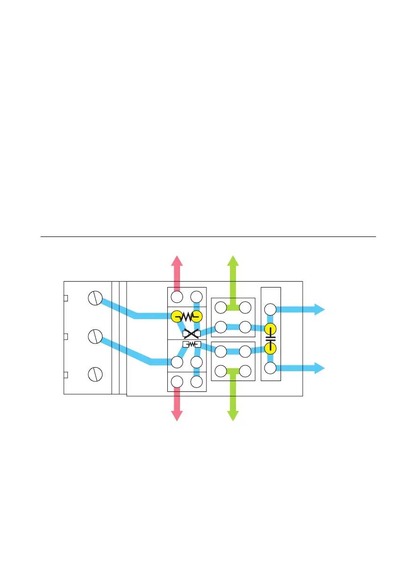
Figure 2-22. SCB-68A Circuit Diagram for Differential Analog Input Lowpass Filter
• Single-ended analog input lowpass filter—To build a single-ended lowpass filter, refer to
Figure 2-23. Add the resistor to position F or G, depending on the AI channel you are using.
Add the capacitor to position B or D, depending on the AI channel you are using. Refer to
Table 2-1 for component positions for all analog input channels.
The SCB-68A ships with a surface mount 0 Ω resistors in the F and G positions. You must
remove the resistor to use the position.
AIi
AIi+8
y
SCx
E
A
F
G
B
C
D
+
+
+
+
5 V AI GND
+
5 V AI GND
AI i
AI i
+
8

 Loading...
