3-2 | ni.com
Chapter 3 Analog Output Waveforms
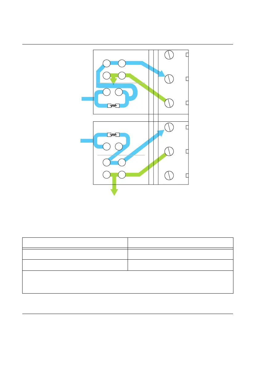
Figure 3-2 illustrates the generic AO channel pad configuration.
Figure 3-2. Analog Output Channel Pad Configuration
Table 3-1 correlates the component labels of the SCB-68A to component locations A and B for
analog output channels 0 and 1.
Lowpass Filtering
Lowpass filters highly or completely attenuate signals with frequencies above the cut-off
frequency, or high-frequency stopband signals. Lowpass filters do not attenuate signals with
frequencies below the cut-off frequency, or low-frequency passband signals. Ideally, lowpass
Table 3-1. Analog Output Channels Component Locations
Channel Positions A
*
and B
†
AO 0 SC8
AO 1 SC9
* A position contains a surface mount 0 Ω resistor; you must remove the resistor to use the position.
If you remove your custom components from the A position, you must reinstall a 0 Ω
resistor.
†
B position contains through hole pads that can be used for two components to be connected in parallel.
56
22
55
21
54
20
SC8
SC9
A
A
B
B
+
+
AO 0
AO 1
AO GND
AO GND
 Loading...

