2-24 | ni.com
Chapter 2 Analog Input and Temperature Sensor Measurements
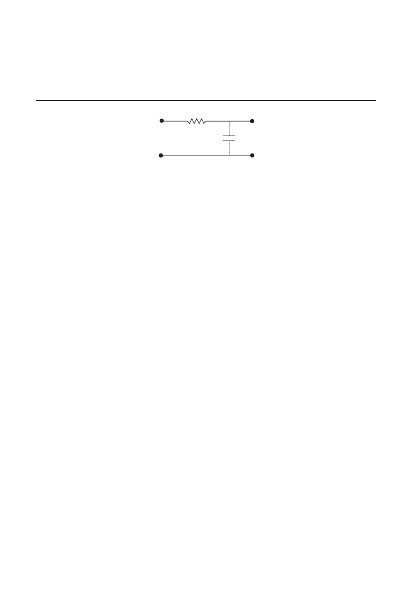
One-Pole Lowpass RC Filter
Figure 2-21 shows the transfer function of a simple series circuit consisting of a resistor (R) and
capacitor (C) when the voltage across R is assumed to be the output voltage (V
m
).
Figure 2-21. Simple RC Lowpass Filter
The transfer function is a mathematical representation of a one-pole lowpass filter, with a time
constant of:
Use Equation 2-1 to design a lowpass filter for a simple resistor and capacitor circuit, where the
values of the resistor and capacitor alone determine f
c
:
(2-1)
where G is the DC gain and s represents the frequency domain.
Selecting Components for Lowpass Filtering
To determine the value of the components in the circuit, fix R (10 kΩ is reasonable) and isolate
C from Equation 2-1 as follows:
(2-2)
The cut-off frequency in Equation 2-2 is f
c
.
For best results, choose a resistor that has the following characteristics:
• Low wattage of approximately 0.125 W
• Precision of at least 5%
• Temperature stability
• Tolerance of 5%
• AXL package (suggested)
• Carbon or metal film (suggested)
Ts()
G
12πRC()s+
-------------------------------=

 Loading...
