3-10 | ni.com
Chapter 3 Analog Output Waveforms
Install resistors in positions A and B and determine the gain according to Equation 3-5:
(3-5)
Analog Output Voltage Dividers
When you use the circuit shown in Figure 3-11 for analog output, the output impedance changes.
Thus, you must choose the values for R
1
and R
2
so that the final output impedance value is as
low as possible. Refer to the device specifications for the output impedance for your device.
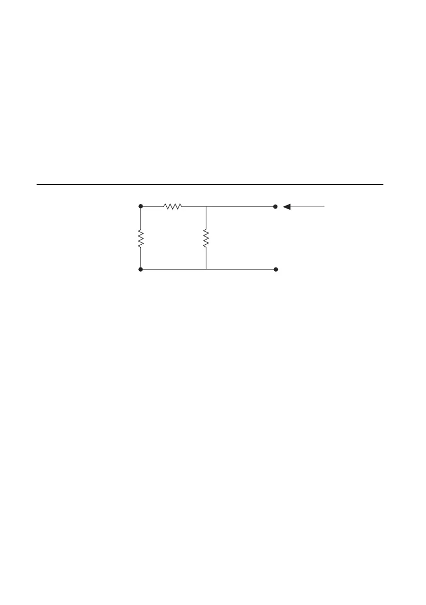
Figure 3-13 shows the electrical circuit you use to calculate the output impedance.
Figure 3-13. Electrical Circuit for Determining Output Impedance
The following equation shows the relationship between R
1
, R
2
, and Z
out
, where Z
out
is the old
output impedance and Z
out2
is the new output impedance:
G
R
B
R
B
R
A
+()
------------------------=
R
2
Output
Impedance
R
1
Z
out
Z
out2
Z
out
R
1
+()R
2
×
Z
out
R
1
R
2
++
----------------------------------------=
 Loading...

