2-38 | ni.com
Chapter 2 Analog Input and Temperature Sensor Measurements
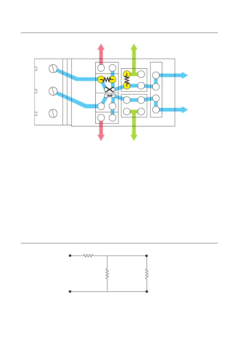
Figure 2-37. SCB-68A Circuit Diagram for Single-Ended Analog Input Attenuation on AI <i>
Install resistors in positions B and F, or positions D and G, depending on the channel you
are using on the SCB-68A. Use the following equation to calculate the gain of the circuit:
where R
B or D
is the resistance of the resistor in position B or D, and R
F or G
is the resistance
of the resistor in position F or G.
Analog Input Voltage Dividers
When calculating the values for R
1
and R
2
, consider the input impedance value from the point of
view of V
in
, as shown in Figure 2-38.
Figure 2-38. Input Impedance Electrical Circuit
The following equation shows the relationship among all of the resistor values:
AIi
AIi+8
y
SCx
E
A
F
G
B
C
D
+
+
+
+
5 V AI GND
+
5 V AI GND
AI i
AI i
+
8
G
R
B orD
R
B orD
R
F orG
+()
-------------------------------------------=
R
2
V
in
+
–
+
–
R
1
Input
Impedance
 Loading...

