© National Instruments | 3-9
NI SCB-68A User Manual
Selecting Components for Attenuating Voltage
To set up the resistors, complete the following steps.
1. Select the value for R
2
(10 kΩ is recommended).
2. Use Equation 3-3 to calculate the value for R
1
.
Base the R
1
calculation on the following values:
• Maximum V
in
you expect from the transducer
• Maximum voltage (<10 VDC) that you want to input to the DAQ device
Accuracy Considerations for Attenuating Voltage
For best results when attenuating voltage, choose a resistor that has the following characteristics:
• Low wattage of approximately 0.125 W
• Precision of at least 5%
• Temperature stable
• Tolerance of 5%
• AXL package (suggested)
• Carbon or metal film (suggested)
Verify that R
1
and R
2
drift together with respect to temperature; otherwise, the system may
consistently read incorrect values.
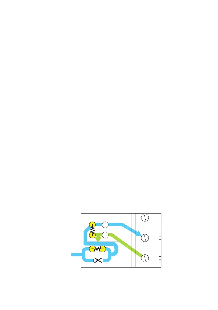
Adding Components for Attenuating Voltage on Analog
Output Signals
To build a two-resistor circuit for attenuating voltages at the AO 0 and AO 1 pins on the
SCB-68A, refer to the pad positions in Figure 3-12. The SCB-68A ships with a surface mount
0 Ω resistor in the A position. You must remove the resistor to use the position. Refer to
Table 3-1 for component positions for both analog output channels.
Figure 3-12. SCB-68A Circuit Diagram for Analog Output Attenuation

 Loading...
