© National Instruments | 5-1
5
Fuse and Power Information
Refer to the Soldering and Desoldering Components on the SCB-68A section of Chapter 1,
Getting Started with the SCB-68A, for more information about adding components and for
soldering and desoldering instructions.
Power Supply Circuitry
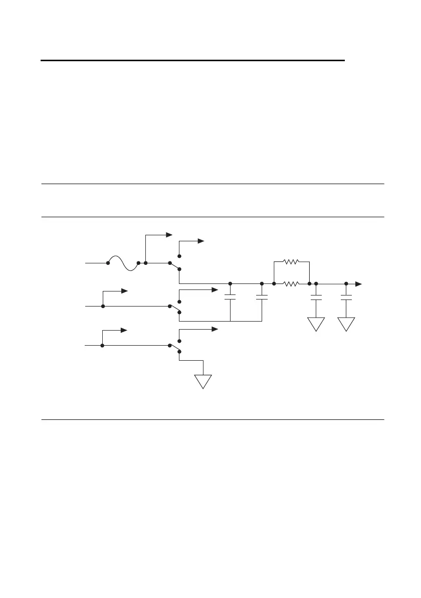
Figure 5-1 shows the power supply circuitry on the SCB-68A.
Figure 5-1. +5 V Power Supply
Fuse
Some DAQ devices provide +5 V power on pin 8 and pin 14. Pin 8 from the DAQ device is
protected by a 1 A self-resetting fuse, shown in Figure 1-2, SCB-68A Printed Circuit Board
Diagram. Shorting pin 8 to ground trips the fuse on the SCB-68A. Pin 14 is not fuse-protected
on the SCB-68A. Shorting pin 14 will cause the fuse on the DAQ device to open.
If the SCB-68A does not work when you power on the DAQ device, check the switch settings
on the SCB-68A and the output fuse (if any) on the DAQ device.
+5 V
(I/O Pin 8)
+5 V Screw Terminal
ACC Not Powered
(NC)
C2
(10 μF)
F1
1 A
S2.2
ACC Powered
C1
(0.1 μF)
R20
(Optional)
R21
C6
(10 μF)
C4
(0.1 μF)
+5 V
Non-MIO
(NC)
MIO
D GND
(I/O Pin 7)
D GND
Screw Terminal
Non-MIO
(NC)
MIO
AI GND
(I/O Pin 56)
AI GND
Screw Terminal
AIAI
AI
S2.3
S2.1

 Loading...
