1-12 | ni.com
Chapter 1 Getting Started with the SCB-68A
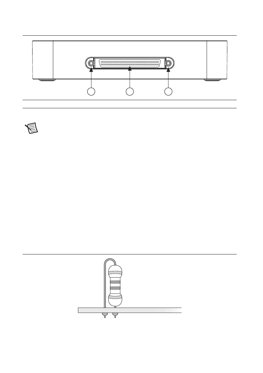
Figure 1-7. SCB-68A Back View
6. Tilt the PCB up and pull it out of the enclosure base.
Note The threaded holes on the SCB-68A for the printed circuit board mounting
should not be used more than five times. Unscrewing and reinstalling the PCB will
produce a compromised connection.
Soldering and Desoldering Guidelines
As you solder and desolder components on the SCB-68A, refer to Figure 1-2.
The SCB-68A ships with surface mount 0 Ω resistors in the F and G positions. You must remove
the resistors to use the positions. Use a low-wattage soldering iron (20 to 30 W) when soldering
to the SCB-68A.
To desolder on the SCB-68A, hot tweezer, low wattage tools work best. Be careful to avoid
damaging the component pads when desoldering. Use only rosin-core electronic-grade solder
because acid-core solder damages the printed-circuit device and components.
The pads on the SCB-68A require that you solder components on in a vertical fashion, as shown
in Figure 1-8.
Figure 1-8. Recommended Resistor Installation
1 68-Pin Connector Screws 2 68-Pin I/O Connector
11 2
 Loading...

