© National Instruments | 3-5
NI SCB-68A User Manual
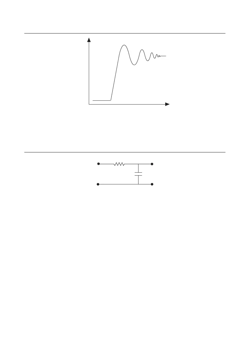
Figure 3-7. Response of a Real Filter to a Square Wave Input Signal
One-Pole Lowpass RC Filter
Figure 3-8 shows the transfer function of a simple series circuit consisting of a resistor (R) and
capacitor (C) when the voltage across R is assumed to be the output voltage (V
m
).
Figure 3-8. Simple RC Lowpass Filter
The transfer function is a mathematical representation of a one-pole lowpass filter, with a time
constant of:
Use Equation 3-1 to design a lowpass filter for a simple resistor and capacitor circuit, where the
values of the resistor and capacitor alone determine f
c
:
(3-1)
where G is the DC gain and s represents the frequency domain.
Time (t)
Volts (V)
Ts()
G
12πRC()s+
-------------------------------=
 Loading...

