EasyManuals Logo
Home>National Instruments>Cables and connectors>SCB-68A

National Instruments SCB-68A User Manual

National Instruments SCB-68A
91 pages
To Next Page IconTo Next Page
To Previous Page IconTo Previous Page
Page #64 background imageLoading...
Page #64 background image
3-4 | ni.com
Chapter 3 Analog Output Waveforms
of the signal. For example, when the square wave, shown in Figure 3-5, enters a filter, an ideal
filter smooths the edges of the input, whereas a real filter causes some ringing in the signal as
the higher frequency components of the signal are delayed.
Figure 3-5. Square Wave Input Signal
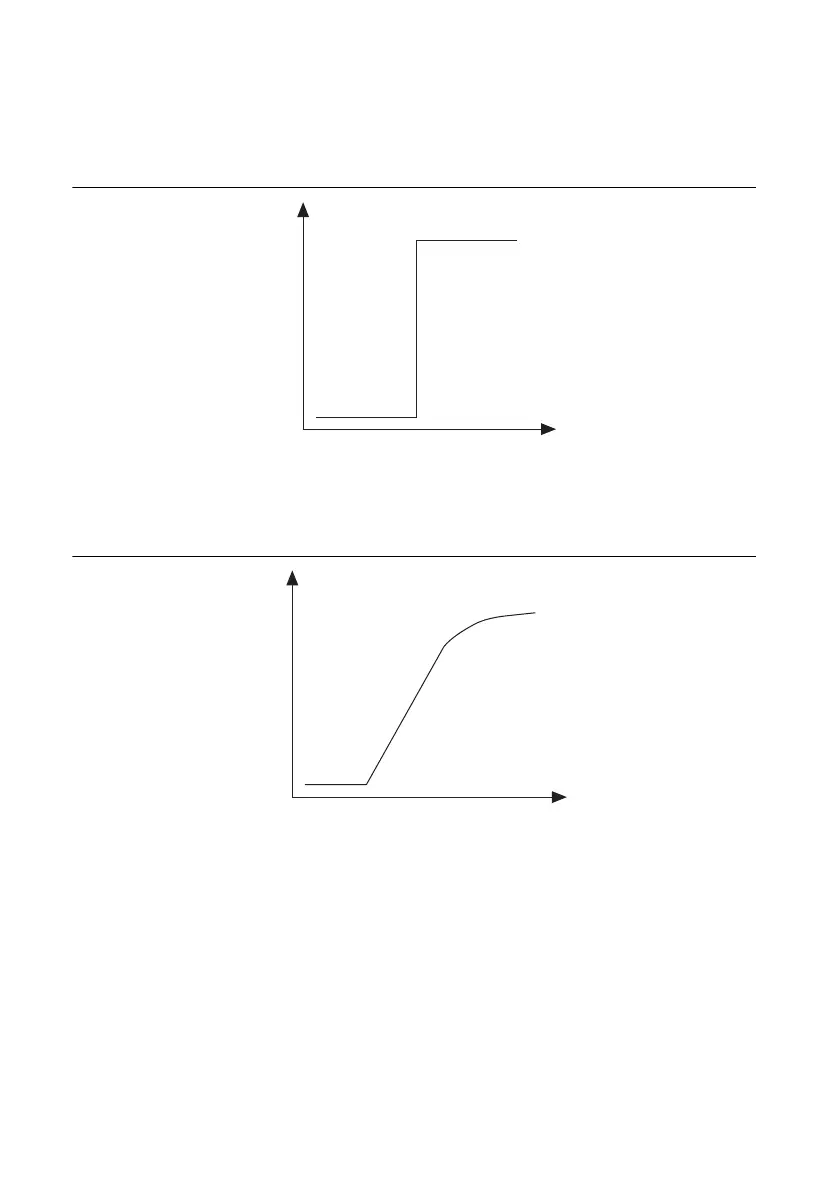
Figures 3-6 and 3-7 show the difference in response to a square wave between an ideal and a real
filter, respectively.
Figure 3-6. Response of an Ideal Filter to a Square Wave Input Signal
Time (t)
Volts (V)
Time (t)
Volts (V)

Table of Contents

Questions and Answers:

Question and Answer IconNeed help?

Do you have a question about the National Instruments SCB-68A and is the answer not in the manual?

National Instruments SCB-68A Specifications

General IconGeneral
BrandNational Instruments
ModelSCB-68A
CategoryCables and connectors
LanguageEnglish

Related product manuals