2-28 | ni.com
Chapter 2 Analog Input and Temperature Sensor Measurements
In practice, highpass filters subject input signals to a mathematical transfer function that
approximates the characteristics of an ideal filter. By analyzing the Bode Plot, or the plot that
represents the transfer function, you can determine the filter characteristics.
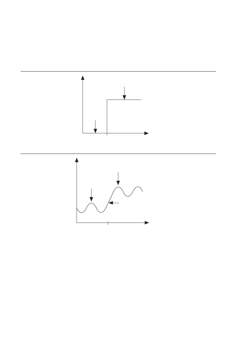
Figures 2-25 and 2-26 show the Bode Plots for the ideal filter and the real filter, respectively, and
indicate the attenuation of each transfer function.
Figure 2-25. Transfer Function Attenuation for an Ideal Filter
Figure 2-26. Transfer Function Attenuation for a Real Filter
Instead of having a gain of absolute zero for frequencies less than f
c
, the real filter has a transition
region between the passband and the stopband, a ripple in the passband, and a stopband with a
finite attenuation gain.
Passband
Stopband
Log Frequency
Gain
f
c
Passband
Stopband
Log Frequency
Gain
f
c
Transition
Region
 Loading...

