157
18.Withtheassistanceofatleastasecondperson,iptheBase
Assembly until the Walking Belt rests on the ground.
Asthemachineisipped,theLiftingShockwillextendand
pivot the Base Frame and Incline Frame Weldments. Be sure
to be clear of any pinch opportunities and not to grasp the
Base Assembly from these shifting parts. Do not grasp the
Walking Belt since it can abruptly move.
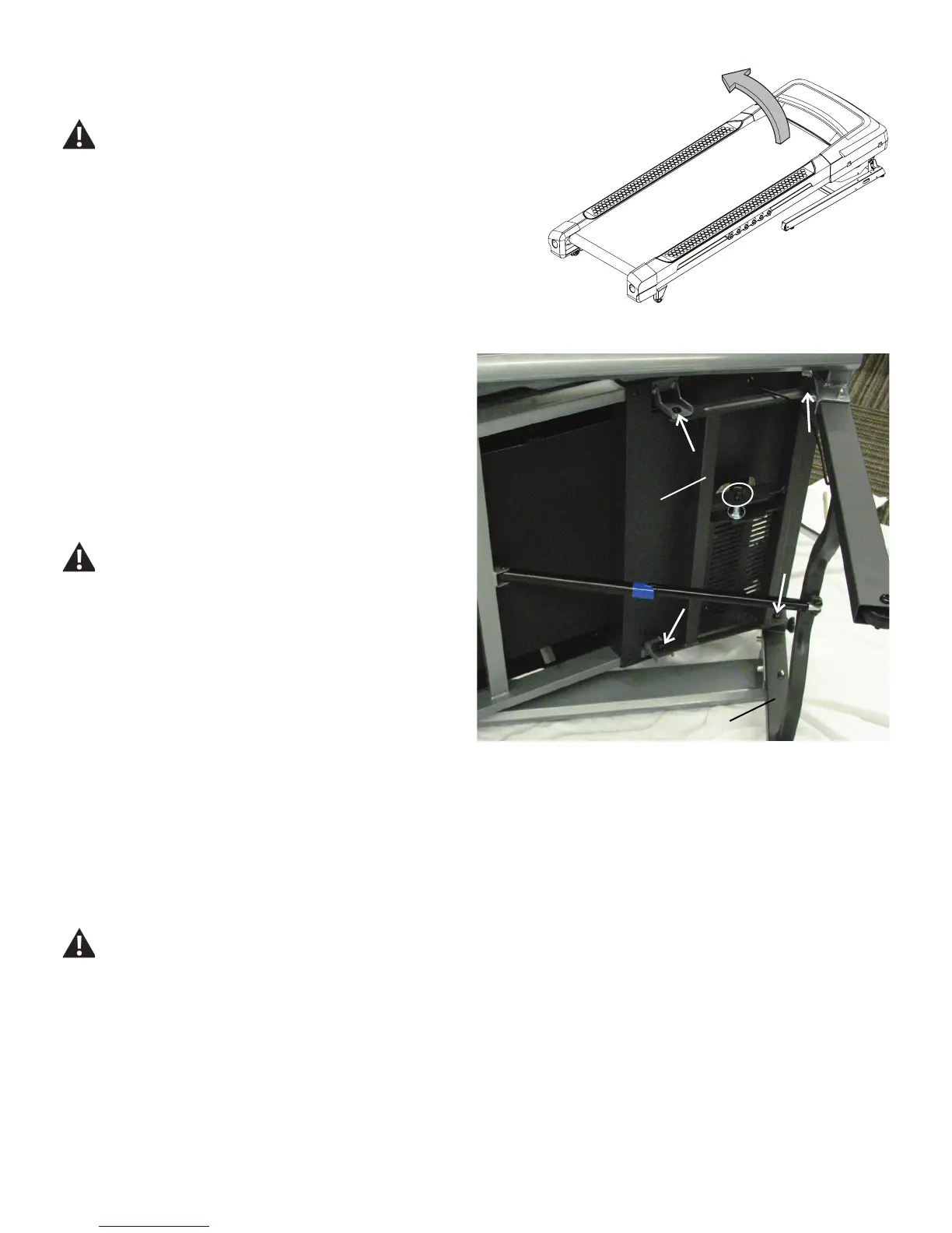
Note: the following image shows the Base Assembly on the side,
notfullyippedandrestingatontheWalkingBelt.TheUprightsare
also still attached.
19. Using a 13mm wrench and a 6mm hex wrench, remove the
indicated hardware (with oval) from the Incline Motor Assembly and
the Incline Weldment.
20. Using a 13mm wrench and a 6mm hex wrench, remove the 4
screws (with arrows) from the Deck Frame and the old Incline Weld-
ment.
Be aware that when the Hardware is released from the Deck
Frame, the Base Frame Weldment may abruptly move since it
will only be supported by the Lift Shock. Be sure to keep clear
of any potential pinch opportunities.
21. Using a 13mm wrench and a 6mm hex wrench, attach the new
Incline Weldment to the Deck Frame.
22. Using a 13mm wrench and a 6mm hex wrench, re-attach the
Incline Weldment to the Incline Motor Assembly.
23.Withtheassistanceofatleastasecondperson,iptheBase
Assembly to the Upright position. Be aware that the Lifting Shock will
begin to compress when placed back to an upright position, lowering
the Base Assembly.
Be sure the area is clear around the Base Assembly before
ippingit.DonotgrasptheWalkingBeltsinceitcanabruptly
move.
Incline Weldment
BaseFrameWeldment
 Loading...