Section 4: Optional Equipment
4-2 Section 4: Optional Equipment Aspila EX Hardware
LED Indications
Setting Up 2PGDAD Module Connections
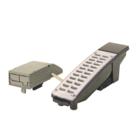
1. Remove the screw from the front of the 2PGDAD module.
Figure 4-2: REMOVE COVER FROM 2PGDAD MODULE
2. Using a screwdriver, break out the plastic piece covering the cable hole.
Figure 4-3: REMOVE PLASTIC COVER FROM CABLE HOLE
LED Indication Note
LED 1 Green LED when
CH1 in use.
Flashing green LED indicates dipswitch setting
and programming for CH1 is conflicting.
LED 2 Green LED when
CH2 in use.
Flashing green LED indicates dipswitch setting
and programming for CH2 is conflicting.
 Loading...
