Section 2: PCB Installation and Startup
Aspila EX Hardware Manual Section 2: PCB Installation and Startup 2-21
2
Analogue Station (8SLIDB) Daughter Board (Figure 2-10 - Figure 2-11)
The 8SLIDB daughter board provides:
• 8 analogue extension ports (used for
analogue telephones, fax machines, ana-
logue modems and connection to voice
mail systems)
• 8 SW1 switches which select constant
current type battery feeding (factory set
to 20mA)
• Connector for 8SLIU PCB
• Ring Generator
• Message Wait Lamping Ability
Note: When connecting a fax
machine, analogue modem or voice
mail make sure to set Program 15-
03-03 to ‘1’ (special terminal) to
allow DTMF during call.
The CN3 and CN5 connectors each provide
connection to 4 analogue station ports and are
not polarity sensitive. The 8SLIDB is
installed on the 8SLIU PCB, with 16 maxi-
mum per system.
Connector Pin-Outs on 8SLIDB
RJ61 Cable Connector - CN3
Pin No. Connection
1 CH12 L1 (tip for port 12)
2 CH11 L1 (tip for port 11)
3 CH10 L1 (tip for port 10)
4 CH9 L2 (ring for port 9)
5 CH9 L1 (tip for port 9)
6 CH10 L2 (ring for port 10)
7 CH11 L2 (ring for port 11)
8 CH12 L2 (ring for port 12)
RJ61 Cable Connector - CN5
Pin No. Connection
1 CH16 L1 (tip for port 16)
2 CH15 L1 (tip for port 15)
3 CH14 L1 (tip for port 14)
4 CH13 L2 (ring for port 13)
5 CH13 L1 (tip for port 13)
6 CH14 L2 (ring for port 14)
7 CH15 L2 (ring for port 15)
8 CH16 L2 (ring for port 16)
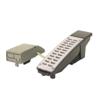
Figure 2-10: 8SLIDB PCB
 Loading...
