Section 2: PCB Installation and Startup
Aspila EX Hardware Manual Section 2: PCB Installation and Startup 2-17
2
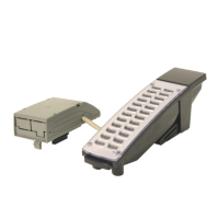
Digital Station (8/16ESIU) PCB (Figure 2-8)
The ESIU PCB provides:
• 8 (8ESIU) or 16 (16ESIU) digital extension circuits (used for digital telephones, DSS consoles,
1SLTAD adapters, 2PGDAD adapters)
• 2 (8ESIU) or 4 (16ESIU) extension status LEDs (each LED indicates status for 4 extensions -
BL1 used for ports 1-4, BL2 for ports 5-8, BL3 for ports 9-12, and BL4 for ports 13-16).
• 1 PCB status LED
• 1 run/block switch
The CN102, CN103, CN202, and CN203 connectors each provide connection to 4 digital station ports.
With the 8ESIU PCB the CN202 and CN203 connectors and the BL3 and BL4 LEDS are removed
from the PCB.
In order to program the system with a multibutton telephone, an 8ESIU or 16ESIU PCB should be
installed. However, system programming can be done using the PCPro or WebPro applications or
through a VoIP telephone. The ESIU requires one universal slot, with a maximum of 16 PCB’s per sys-
tem.
The ESIU connections are not polarity sensitive to the digital extensions.
Connector Pin-Outs on ESIU
RJ61 Cable Connector - CN102, CN103, CN202, CN203
Pin No. Connection
1port 4
2port 3
3port 2
4port 1
5port 1
6port 2
7port 3
8port 4
 Loading...
