A-3
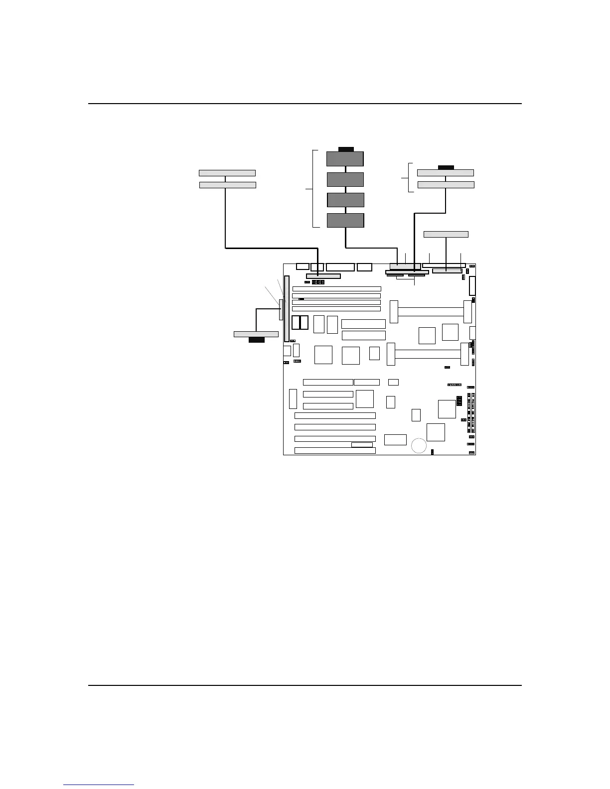
System Cabling
Figure A-1. Standard System Cable Configuration
E
I
F
H
P
Q
D
N
O
G
M
J
K
D
C
B
A
A
L
S
R
T
U
A.
Device internal SCSI termination
resistors
B.
Optional narrow SCSI devices in upper
peripheral bays
C.
Narrow SCSI interface cable
D.
Narrow SCSI connector (50 pin)
E.
Internal SCSI termination resistors
(not installed when optional internal
narrow SCSI devices are used)
F.
3.5-inch diskette drive
G.
Front panel connector
H.
Diskette interface cable
I.
Diskette drive connector
J.
Wide SCSI connector (68 pin)
K.
Wide SCSI interface cable
L.
Wide SCSI Hard disk drives in
internal bays
M.
System board
N.
I/O riser board
O.
External narrow SCSI cable
P.
External narrow SCSI device
Q.
SCSI terminator
R.
IDE CD-ROM drive (master device)
S.
IDE Tape drive (slave device)
T.
IDE interface cable
U.
IDE connector