u
Fig. 43
occupies a position other than those described above, then
loosen first the two screws " E " of the worm gear " F " (Fig, 45),
hold the balance wheel firmly, thus keeping the needle bar in its
highest position, and, by hand, turn the worm gear " F " around
the upper shaft until the eccentric " A " is in position I or position
II (Fig. 42).
After this adjustment firmly tighten the two screws " E " (Fig.
45).
The timing of the zig-zag movement and the movement of the
needle bar can also be performed with the aid of the gauge
10-4.
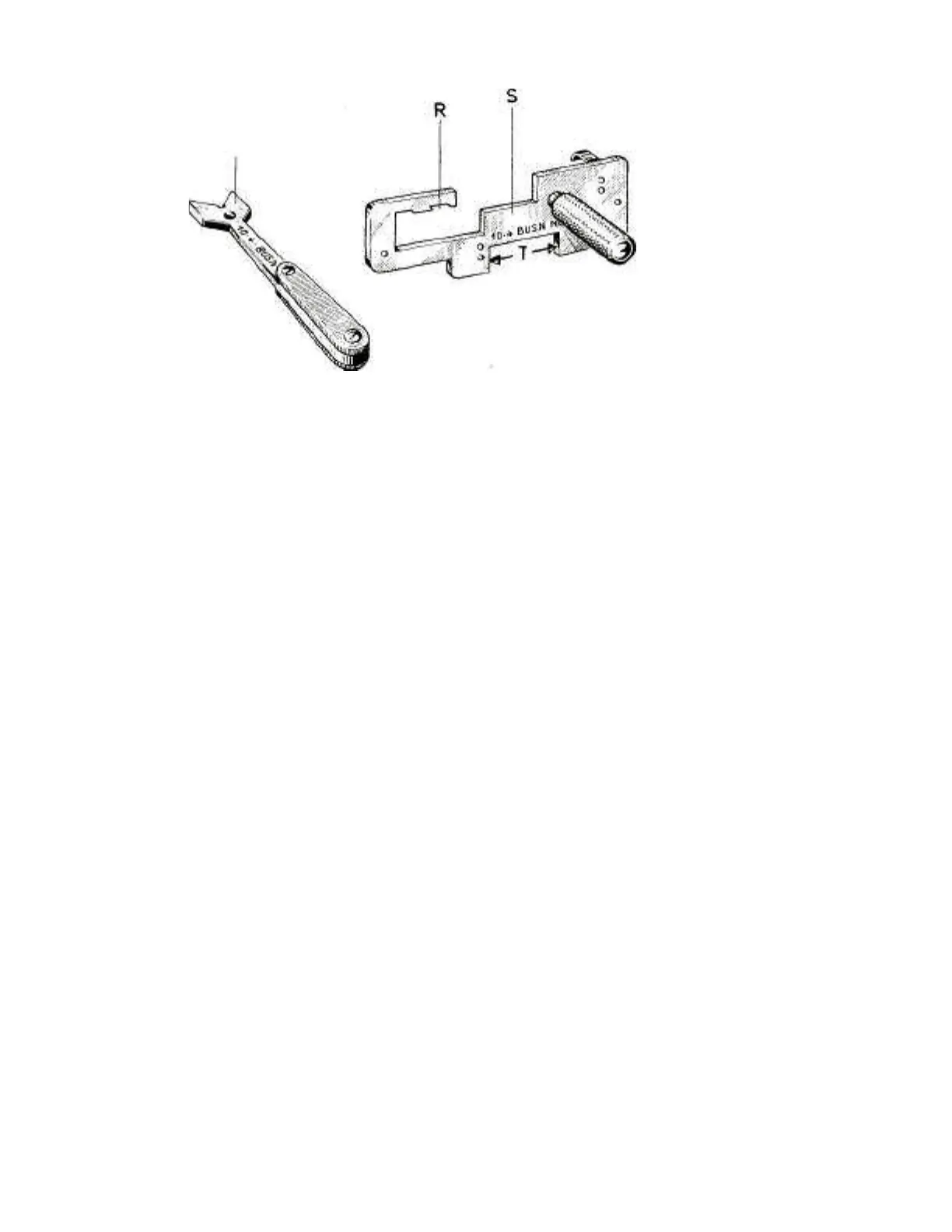
The gauge 10-4, shown in Fig. 43, consists of:
A plate " S " with a knurled stud serving as a holder.
During the timing operation this plate " S " replaces the zig-zag
mechanism cover plate. The notch " R " serves for positioning
of the needle positioning lever and the space " T " is required for
the zig-zag width lever.
A small steel plate " U ", with a handle-shaped portion at one end
and a V-shaped cut-out at the other end.