Now the lever assembly for zig-zag width control " 17 " is free
to be dismantled in the following order:
Remove the feed eccentric connecting rod No. D 85506 (see
chapter, “Removing of Feed Eccentric Connecting Rod ").
Turn the fly wheel (balance wheel) so that the fork of the
oscillating rock shaft No. 21230 is in its highest position.
Turn the vertical shaft " 31 " (around its own axle) so that
the small lever " 36 " is completely to the right.
Push link " 35 " to the back of the arm so that it is almost under
the lever " 36 ".
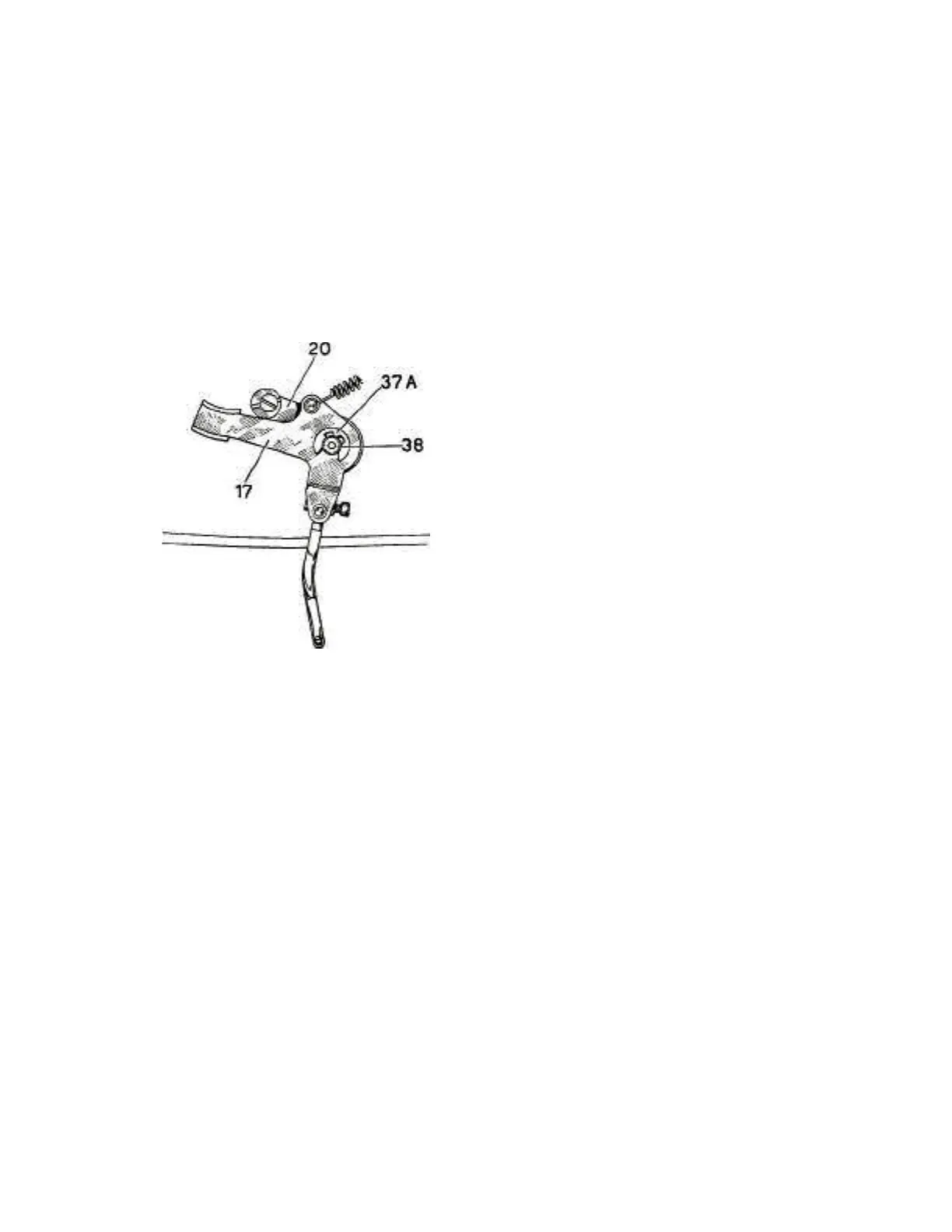
Remove retaining ring " 37A " from pin " 38 " of the lever
Fig. 48
Assembly for zig-zag width control " 17 ". (The pin " 38 " must
not be taken out).
/) Remove the lever assembly for zig-zag width control " 17 "
and the zig-zag width regulating lever " 20 ".