g)
The bearing bushing " E " of the lever assembly must be set
down on washer " 14 " and retaining ring " 11B " without force.
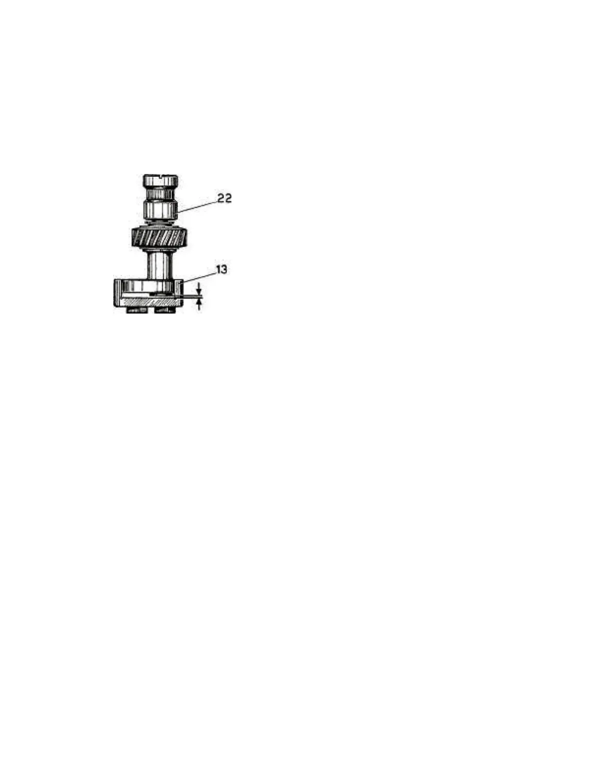
Adjust the clearance (open distance) between the underside
of the eccentric " 22 " (see Fig. 50) and the channel of the
lever assembly " 13 " so that there is a free space of about
0,02" (see Fig. 51).
about 0,02"
Fig. 51
h) Tighten securely screw " 2 " which holds pin " 15 " in the
hole of the upper arm (Fig. 50).
Place the sector " 21 " (Fig. 46) on the short stud in the link " 35
" of the vertical shaft, then let the sector " 21 " move into the
groove underneath the lever assembly " 13 ".
/') Take the needle bar positioning lever » " 12 " (Figs. 46 and 47)
and introduce it between the upper shaft and the rear wall of the
machine in such a manner that its handle " C " passes below
the upper shaft and through the front opening of the
machine (Fig. 47). The lever bearing " D " of this same lever
assembly " 12 " must be slipped over the pin " 15 ".
Slip retaining ring " 11A " into the upper groove of the pin " 15". 1)
Attach spring " 10 " (Fig. 52). m) Attach spring " 30 " (Fig. 52).
n) Replace the needle bar positioning rod " 7 " (Fig. 46) from
the face plate side of the machine and insert its right-hand end
into the hole of the block " 27 ". Connect this rod " 7 " with a
needle